Fluid-filled vibration damping device

Active Publication Date: 2015-09-10
TOKAI RUBBER IND LTD
View PDF12 Cites 23 Cited by
  • Summary
  • Abstract
  • Description
  • Claims
  • Application Information

AI Technical Summary

Benefits of technology

[0046]With the fourteenth mode, by using a concave crushed part that has an asymmetrical inner surface shape, the caulking engaging part that prevents falling out that is engaged at the back part of the fixing part can be formed with more stability. Specifically, this concave crushed part is formed by implementing the crushing and caulking process at the opening end surface of the insertion port of the sealing coupling member using a punch shaped jig or the like, for example, but by biasing the deepest position of the crushed part to the groove bottom surface side of the clasping groove, the depth of the crushed part is suppressed and problems such as breaking or the like of the sealing coupling member is avoided, and thickness deviation by the crushed part can be efficiently created at the groove bottom surface side of the clasping groove, and it is possible to form the caulking engaging part that engages with the back part of the fixing part.
[0047]With the present invention, wit

Problems solved by technology

However, when trying to ensure fluid tightness of the fluid chamber with the vibration damping device main unit alone, it is necessary to use large axial dimensions for the second mounting member for providing a seal structure, and it was difficult to make the vibration damping device main unit more compact in the axial direction.
Furthermore, when an attempt is made to constitute a seal structure of the fluid chamber by doing press fitting or the like of a flexible film fixing ring on the second mounting member in a tank filled with non-compressible fluid, dimensional accuracy of the second mountin

Method used


Image

  • Fluid-filled vibration damping device
  • Fluid-filled vibration damping device
  • Fluid-filled vibration damping device

Examples


first embodiment

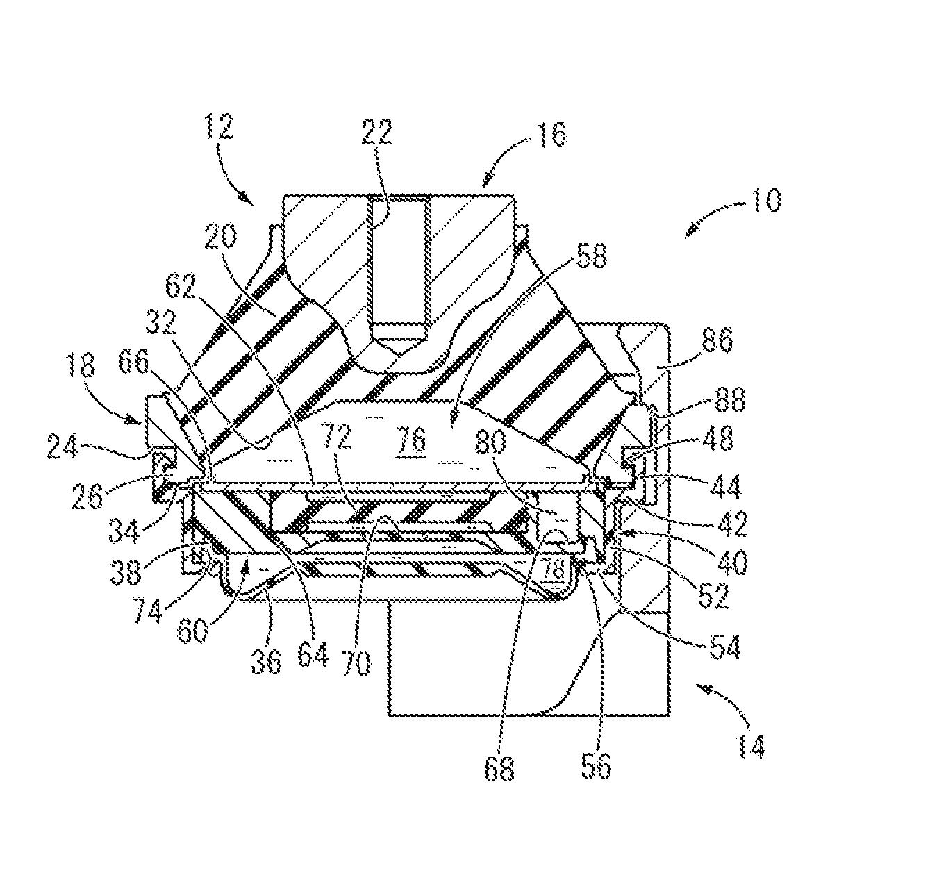
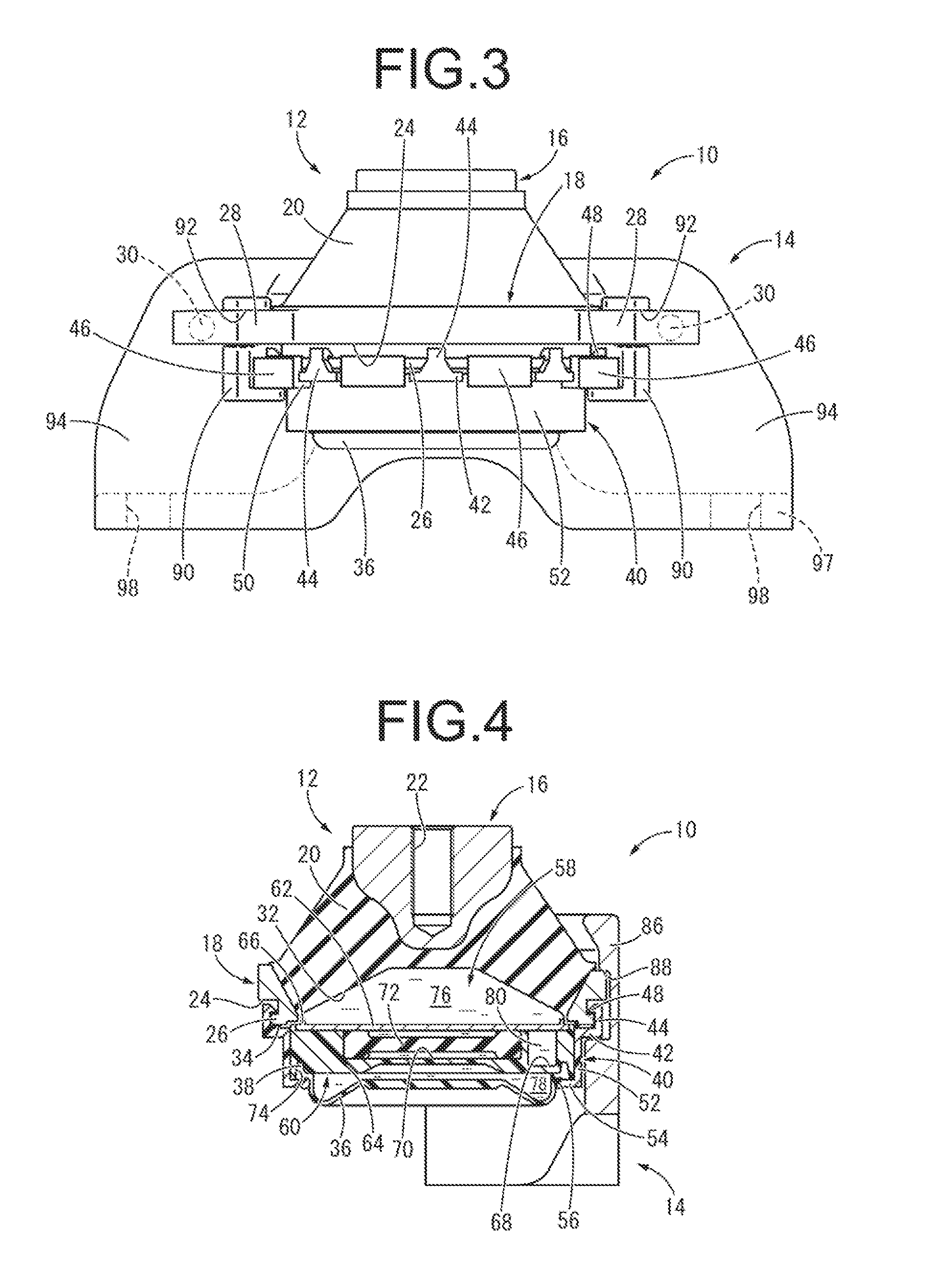
[0093]FIGS. 1 to 6 show an automobile engine mount 10 as the fluid-filled vibration damping device constituted according to the present invention. The engine mount 10 has a constitution for which a sealing coupling member 14 is mounted on a mount body 12 as the vibration damping device main unit, and the mount body 12 has a constitution for which a first mounting member 16 and a second mounting member 18 are mutually elastically connected by a main rubber elastic body 20. With this embodiment, the constitution has a bracket part formed as an integrated unit with the sealing coupling member 14. With the description below, as a rule, the vertical direction means the vertical direction in FIG. 3 which is the mount axial direction.

[0094]In more specific detail, the first mounting member 16 is a highly rigid member formed using an iron or aluminum alloy, a hard synthetic resin or the like, and exhibits a solid, roughly circular block shape. Furthermore, a screw hole 22 that opens at the ...

third embodiment

[0141]FIGS. 19 and 20 show an engine mount 130 as the present invention. The engine mount 130 has a constitution by which a sealing coupling member 134 is attached to a mount body 132. The mount body 132 has a constitution for which the first mounting member 16 and a second mounting member 135 are elastically connected by the main rubber elastic body 20.

[0142]The second mounting member 135 has a roughly round ring shape equipped with a locking groove 24 that opens at the outer circumference surface, and is equipped with a fixing flange 136 projecting to the outer circumference side.

[0143]Furthermore, two fitting convex parts 138, 138 projecting facing downward are each integrally formed on both the left and right side parts of the fixing flange 136 for which the projection dimensions are made partially larger.

[0144]Meanwhile, the sealing coupling member 134 has a thin walled, large diameter mounting part 140 that exhibits a roughly round tube shape. Furthermore, an inner flange shap...

fourth embodiment

[0152]In FIGS. 23 to 28, an engine mount 150 is shown as the present invention. This engine mount 150 is constituted with a sealing coupling member 154 shown in FIGS. 31 and 32 mounted on a mount body 152 as the vibration damping device main unit shown in FIGS. 29 and 30. With the description hereafter, the vertical direction means as a rule the vertical direction in FIG. 23 which is the mount axial direction.

[0153]In more specific detail, as shown in FIGS. 29 and 30, the mount body 152 is constituted so that a first mounting member 156 and a second mounting member 158 are elastically connected to each other by a main rubber elastic body 160.

[0154]The first mounting member 156 has a roughly rectangular tube shape equipped with a hollow hole 162 extending straight, and a highly rigid member is used that is formed using iron or an aluminum alloy, a rigid synthetic resin or the like. Also, the first mounting member 156 is arranged with a center axis extending in a direction roughly per...


PUM


Abstract

A fluid-filled vibration damping device including a vibration damping device main unit which has a main rubber elastic body elastically connecting first and second mounting members, and a fluid chamber whose wall is partially constituted by the main rubber elastic body. The vibration damping device main unit further includes a temporary joint member locked on the second mounting member and temporarily coupled thereto in an axial direction, and an annular sealing part provided to the temporary joint member and overlapped on the second mounting member in the axial direction with a sealing rubber sandwiched therebetween for achieving a temporary seal. A sealing coupling member is mounted on the second mounting member while exerting a pressing force in a direction of overlapping on the second mounting member and the temporary joint member for increasing a compression ratio of the sealing rubber and achieving a full seal.

Description

INCORPORATED BY REFERENCE[0001]The disclosure of Japanese Patent Application Nos. 2013-187656 filed on Sep. 10, 2013 and 2013-187659 filed on Sep. 10, 2013, each including the specification, drawings and abstract is incorporated herein by reference in its entirety. This is a Continuation of International Application No. PCT / JP2014 / 070645 filed on Aug. 5, 2014.BACKGROUND OF THE INVENTION[0002]1. Field of the Invention[0003]The present invention relates to a fluid-filled vibration damping device used for an automobile engine mount or the like.[0004]2. Description of the Related Art[0005]From the past, a fluid-filled vibration damping device has been known which is interposed between members constituting a vibration transmission system, which is one type of vibration damping support unit or vibration damping coupling unit which does mutual vibration damping connection of those members. The fluid-filled vibration damping device has a first mounting member and a second mounting member el...

Claims


Application Information

Patent Timeline
IPC IPC(8): F16F13/08
CPCF16F13/085F16F13/08F16F13/103F16F2230/30
Inventor MURAOKA, MUTSUMISUZUKI, TOMOMIOKUMURA, KEIMICHIYAMA, WAKAKO
Owner TOKAI RUBBER IND LTD
Why Eureka
Try Eureka