
In-Service Optical Time Domain Reflectometry Utilizing Raman Pump Source

a technology of optical time domain reflectometry and raman pump source, which is applied in the direction of reflectometers using simulated back-scatter, optical apparatus testing, instruments, etc., can solve the problems of only being able to perform type of testing, exposing various pieces of equipment to damage, and not being able to periodically take a portion of the system out of servi

Active Publication Date: 2015-09-10
II VI DELAWARE INC
View PDF4 Cites 21 Cited by
  • Summary
  • Abstract
  • Description
  • Claims
  • Application Information

AI Technical Summary

Benefits of technology

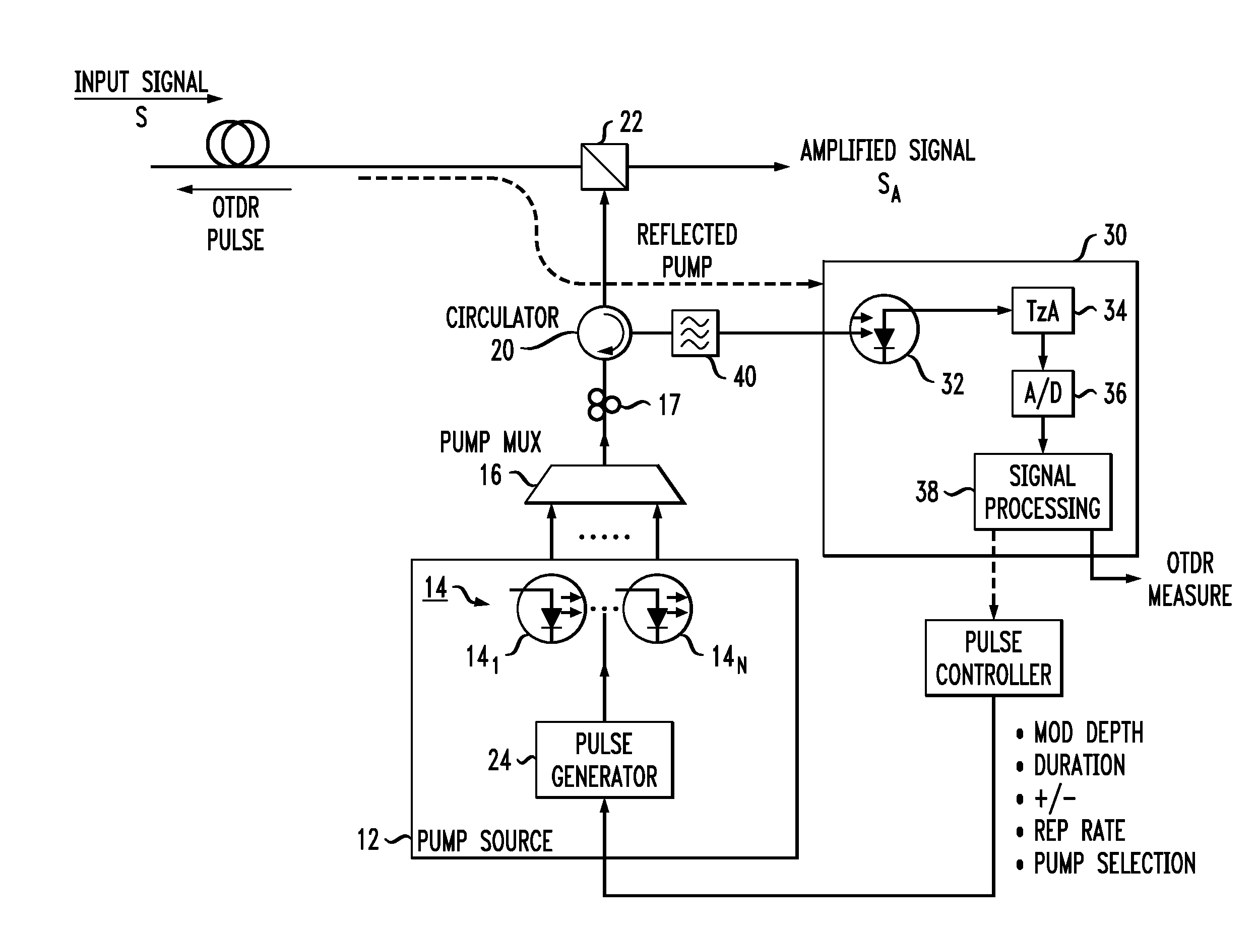
The present invention is about improving a DRA system to measure the health of optical devices in real-time while still amplifying the optical data signal. This is done by adding special pulses to the system that ride above or below the primary pump signal. These pulses are timed in a way that they only encounter a single optical signal as it passes through the device being measured. By doing this, the system can perform necessary health checks without interfering with the overall goal of amplifying the optical data signal. The reflected pulses are then removed and evaluated in a way similar to conventional OTDR systems. The technical effect is improved in-service health monitoring for optical devices.

Problems solved by technology

This is especially a concern in the central office (CO) environment, where high Raman pump powers could emit unsafe levels of optical power and expose various pieces of equipment to damage (as well as personnel to injury at the CO location).
While advances have been made that utilize a Raman pump source itself to create the pulses used for OTDR measurements, this type of testing can only be performed when the system is otherwise not in service (i.e., when the Raman pump sources are not being used as create gain in propagating transmission signals).
For this collection of long-term data, it is not feasible to periodically take a portion of a system out of service, perform an OTDR measurement, and then bring the system back on line, as would be required if the conventional method of using Raman pumps was employed.

Method used


Image

  • In-Service Optical Time Domain Reflectometry Utilizing Raman Pump Source
  • In-Service Optical Time Domain Reflectometry Utilizing Raman Pump Source
  • In-Service Optical Time Domain Reflectometry Utilizing Raman Pump Source

Examples


Embodiment Construction

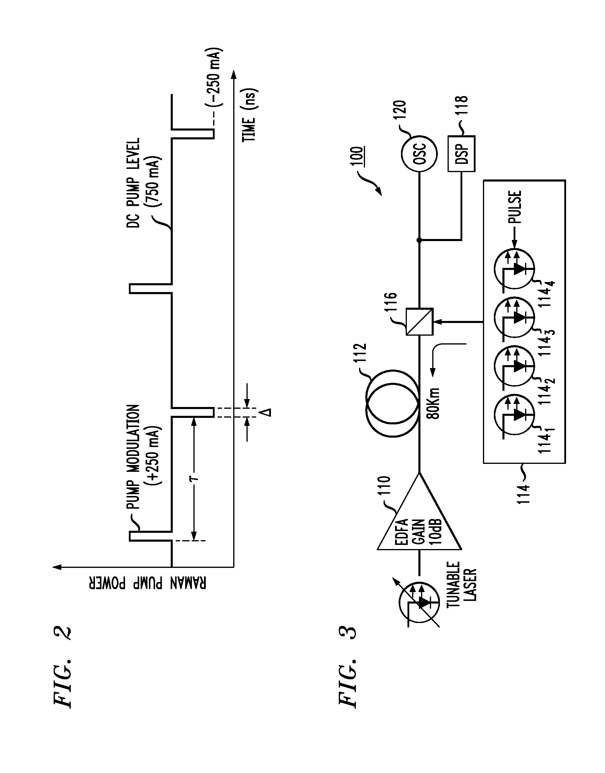
[0022]An arrangement for providing “in-service” (i.e., “live”) OTDR measurements is proposed in accordance with the present invention that is able to utilize a Raman pump source to provide OTDR pulses while it continues to operate in its primary role as creating gain in the propagating optical transmission signal. In accordance with the teachings of the present invention, a Raman pump source is momentarily pulsed to either a higher or lower level than that nominally used for the amplifying process. The OTDR pulse is configured to have a relatively short duration on the order of, for example, tens to hundreds of nanoseconds, and will travel along the fiber span and be reflected in the manner well-understood for the purposes of OTDR measurements.

[0023]As will be explained in detail below, the pulses are preferably timed to have an extremely long repetition interval so that an optical transmission signal propagating along the fiber being measured would only encounter a single OTDR puls...


PUM


Abstract

An arrangement for providing real-time, in-service OTDR measurements in an optical communication system utilizing distributed Raman amplification. One or more of the laser diodes used to provide the pump light necessary to create optical gain is modified to also generate short duration pulses that ride above or below the conventional pump light. These short duration pulses (which co-exist with the pump light within the optical fiber) are used in performing OTDR measurements, with a conventional processing system used to evaluate reflected pulses and create the actual OTDR measurements.

Description

CROSS-REFERENCE TO RELATED APPLICATIONS[0001]This application claims the benefit of U.S. Provisional Application No. 61 / 950,116, filed Mar. 9, 2014 and herein incorporated by reference.TECHNICAL FIELD[0002]The present invention relates to performing optical time domain reflectometry (OTDR) measurements and, more particularly, to a configuration for performing on-going OTDR measurements for in-service optical transmission systems utilizing distributed Raman amplification.BACKGROUND OF THE INVENTION[0003]The ever-increasing demand for optical bandwidth continues to drive the need for faster data transmission rates, which then requires improvements in system performance for parameters such as optical signal to noise ratio (OSNR). While some attempts in improving OSNR involve changes in the coding schemes utilized to perform the data transmission, other attempts are directed to improving the optical properties of the transmission channel itself. For example, amplification of the optical...

Claims


Application Information

Patent Timeline
IPC IPC(8): G01M11/00H01S3/30
CPCH01S3/302G01M11/3127G01M11/319H01S3/094003H01S3/094076H01S3/09415H01S3/0014
Inventor GURUSAMI, ARAVANANZAHNLEY, TIMOTHY K.DAHL, SCOTTWILLIAMS, MARTIN R.MCCLEAN, IAN P.
Owner II VI DELAWARE INC
Learn More