
Electronic Device With Dual Clutch Barrel Cavity Antennas

a technology of electronic devices and antennas, applied in the field of electronic devices with antennas, can solve the problems of difficulty in forming electronic device antenna structures with desired attributes, affecting performance, and affecting device siz

Active Publication Date: 2015-09-10
APPLE INC
View PDF4 Cites 32 Cited by
  • Summary
  • Abstract
  • Description
  • Claims
  • Application Information

AI Technical Summary

Benefits of technology

The patent text describes an electronic device with antennas that may be cavity antennas. The device has a metal housing with hinges and a clutch barrel region between the hinges where the cavity antennas may be formed. The cavity antennas may have flexible printed circuits and components such as speakers may be mounted within them while being isolated from the antennas using inductors. The technical effect of the patent is the improved performance of electronic devices with antennas that can be placed within a metal housing and have an improved signal quality.

Problems solved by technology

It can be challenging to form electronic device antenna structures with desired attributes.
Antenna performance may not be satisfactory if the housing structures are not configured properly and interfere with antenna operation.
Device size can also affect performance.
It can be difficult to achieve desired performance levels in a compact device, particularly when the compact device has conductive housing structures.

Method used


Image

  • Electronic Device With Dual Clutch Barrel Cavity Antennas
  • Electronic Device With Dual Clutch Barrel Cavity Antennas
  • Electronic Device With Dual Clutch Barrel Cavity Antennas

Examples


Embodiment Construction

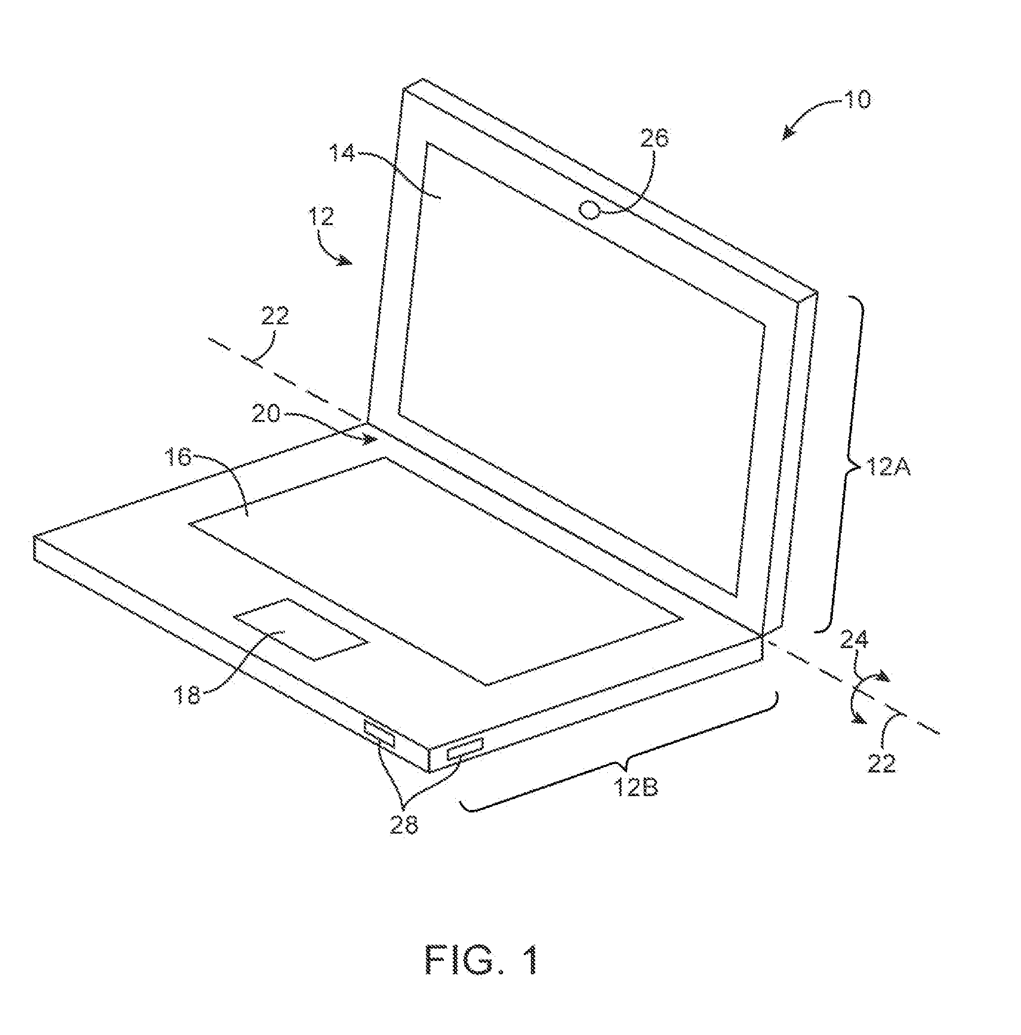
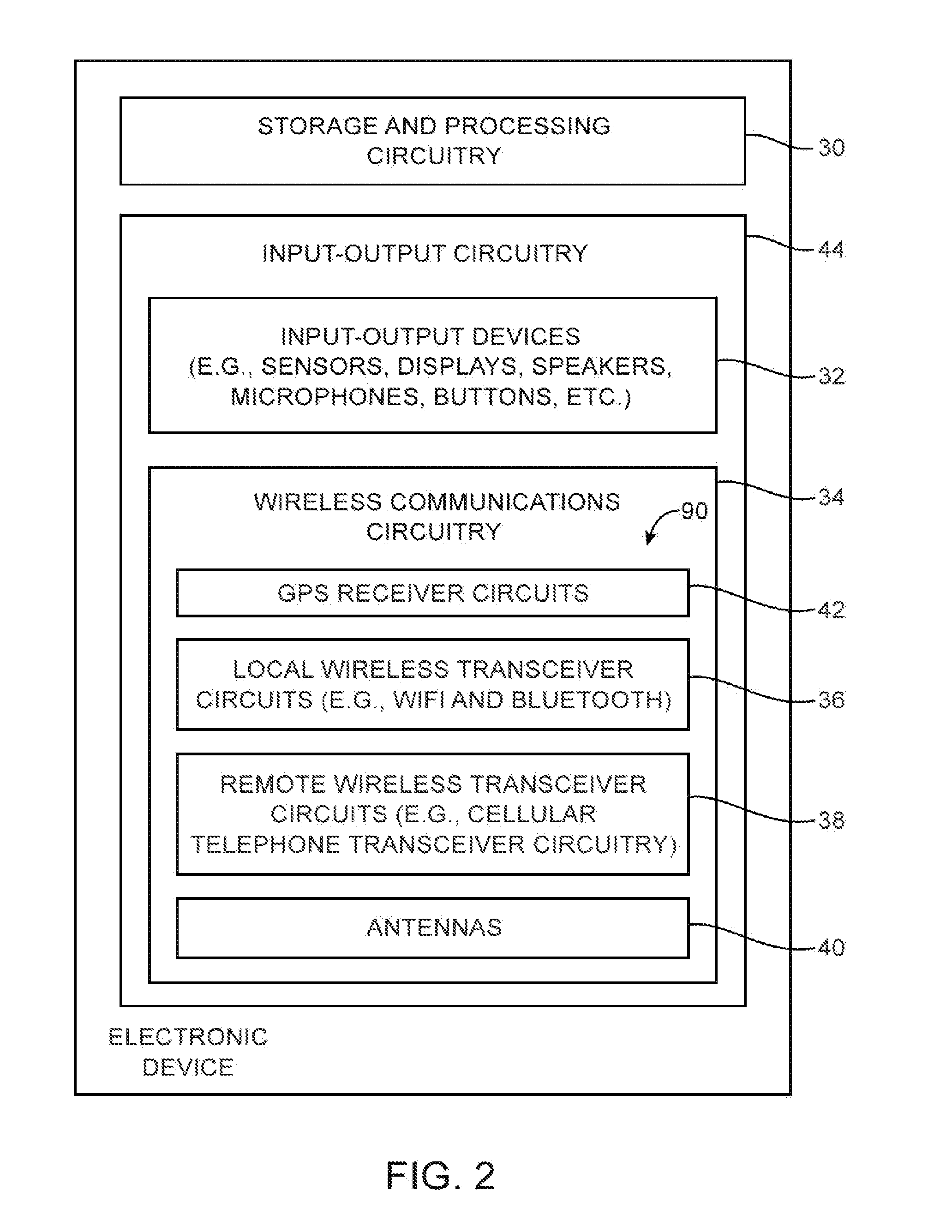
[0020]An electronic device such as electronic device 10 of FIG. 1 may contain wireless circuitry. For example, electronic device 10 may contain wireless communications circuitry that operates in long-range communications bands such as cellular telephone bands and wireless circuitry that operates in short-range communications bands such as the 2.4 GHz Bluetooth® band and the 2.4 GHz and 5 GHz WiFi® wireless local area network bands (sometimes referred to as IEEE 802.11 bands or wireless local area network communications bands). Device 10 may also contain wireless communications circuitry for implementing near-field communications, communications at 60 GHz, light-based wireless communications, satellite navigation system communications, or other wireless communications.

[0021]Device 10 may be a handheld electronic device such as a cellular telephone, media player, gaming device, or other device, may be a laptop computer, tablet computer, or other portable computer, may be a desktop com...


PUM


Abstract

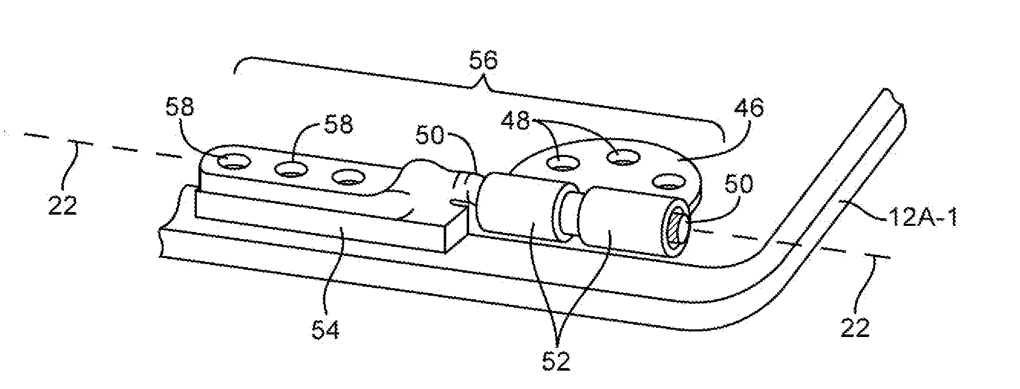
An electronic device has antennas formed from cavity antenna structures. The electronic device may have a metal housing. The metal housing may have an upper housing in which a component such as a display is mounted and a lower housing in which a component such as a keyboard is mounted. Hinges may be used to mount the upper housing to the lower housing for rotation about a rotational axis. Cavity antennas may be formed in a clutch barrel region located between the hinges and running along the rotational axis. A flexible printed circuit may be formed between the cavity antennas. Each cavity antenna may have a first end that is adjacent to one of the hinges and a second end that is adjacent to the flexible printed circuit. Cavity walls for the cavity antennas may be formed from metal housing structures such as metal portions of the lower housing.

Description

BACKGROUND[0001]This relates generally to electronic devices and, more particularly, to electronic devices with antennas.[0002]Electronic devices often include antennas. For example, cellular telephones, computers, and other devices often contain antennas for supporting wireless communications.[0003]It can be challenging to form electronic device antenna structures with desired attributes. In some wireless devices, the presence of conductive housing structures can influence antenna performance. Antenna performance may not be satisfactory if the housing structures are not configured properly and interfere with antenna operation. Device size can also affect performance. It can be difficult to achieve desired performance levels in a compact device, particularly when the compact device has conductive housing structures.[0004]It would therefore be desirable to be able to provide improved wireless circuitry for electronic devices such as electronic devices that include conductive housing ...

Claims


Application Information

Patent Timeline
Patent Type & Authority Applications(United States)
IPC IPC(8): H01Q1/22
CPCH01Q1/2266G06F1/1681G06F1/1683H01Q9/42H05K9/0054H01Q13/18H05K1/028H05K1/0224H05K1/0215
Inventor GUTERMAN, JERZYLI, QINGXIANGPASCOLINI, MATTIA
Owner APPLE INC
Learn More