Medical image display apparatus, method, and medium

a technology of medical image and display apparatus, applied in the field of medical image display apparatus, method, can solve the problem that the intuitive understanding of the distance between the puncture guide line and the puncture line is difficult, and achieve the effect of accurately confirming the position of the puncture target in the cross-sectional imag

Active Publication Date: 2015-09-17
FUJIFILM CORP
View PDF5 Cites 5 Cited by
  • Summary
  • Abstract
  • Description
  • Claims
  • Application Information

AI Technical Summary

Benefits of technology

[0033]In a case in which the index is generated separately from the three-dimensional image, by allowing at least two of display, non-display, and translucent display of the index on the cross-sectional image to be switched, the index may be hidden or displayed translucently so as not to hindering when puncturing, so that the position of the puncture target in the cross-sectional image may be confirmed accurately.

Problems solved by technology

The method described in Japanese Unexamined Patent Publication No. 2012-040220, however, requires that changes in the size of the two distance marks need to be constantly confirmed, so that the sense of distance between the puncture guide line and the puncture line is difficult to understand intuitively.

Method used


Image

  • Medical image display apparatus, method, and medium
  • Medical image display apparatus, method, and medium
  • Medical image display apparatus, method, and medium

Examples


Embodiment Construction

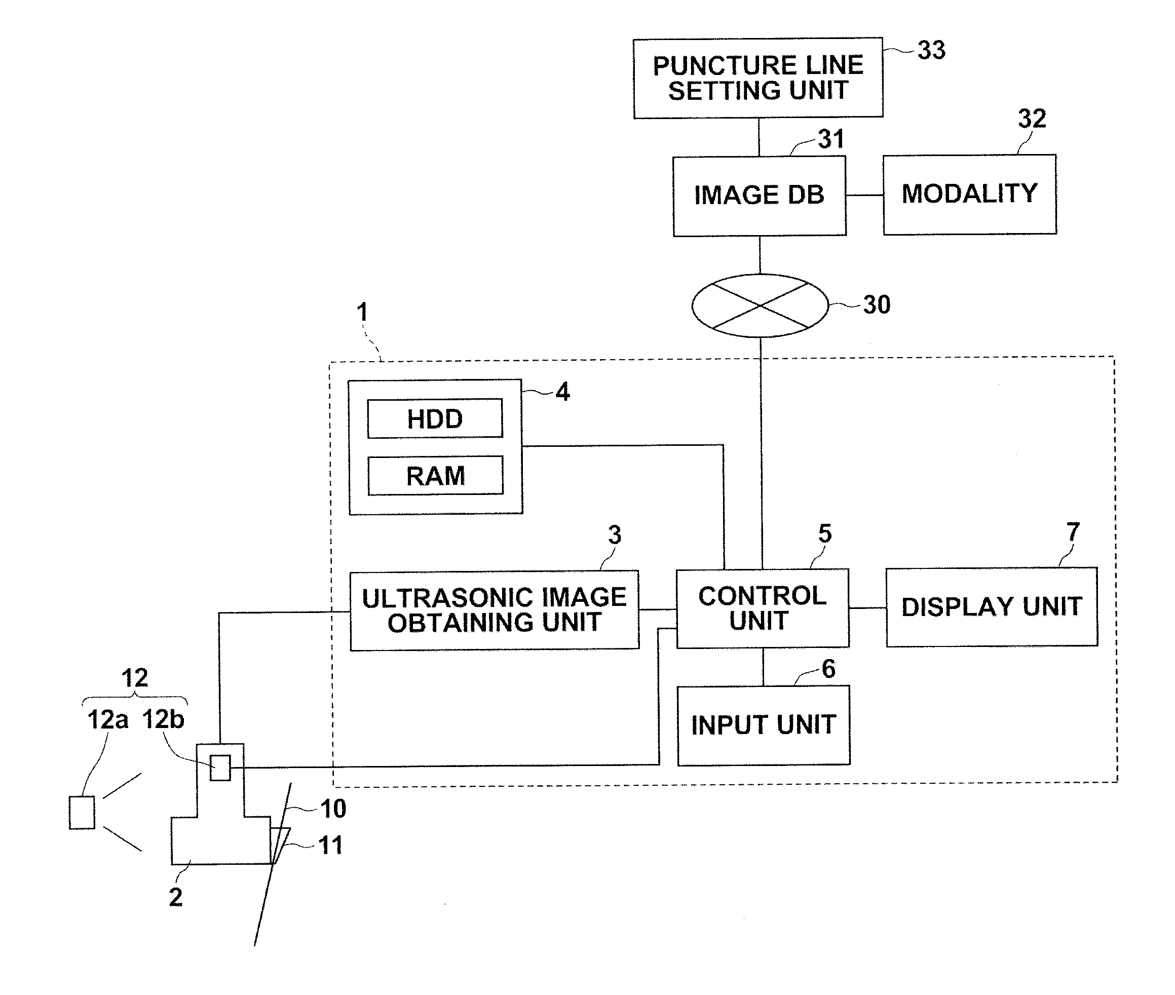
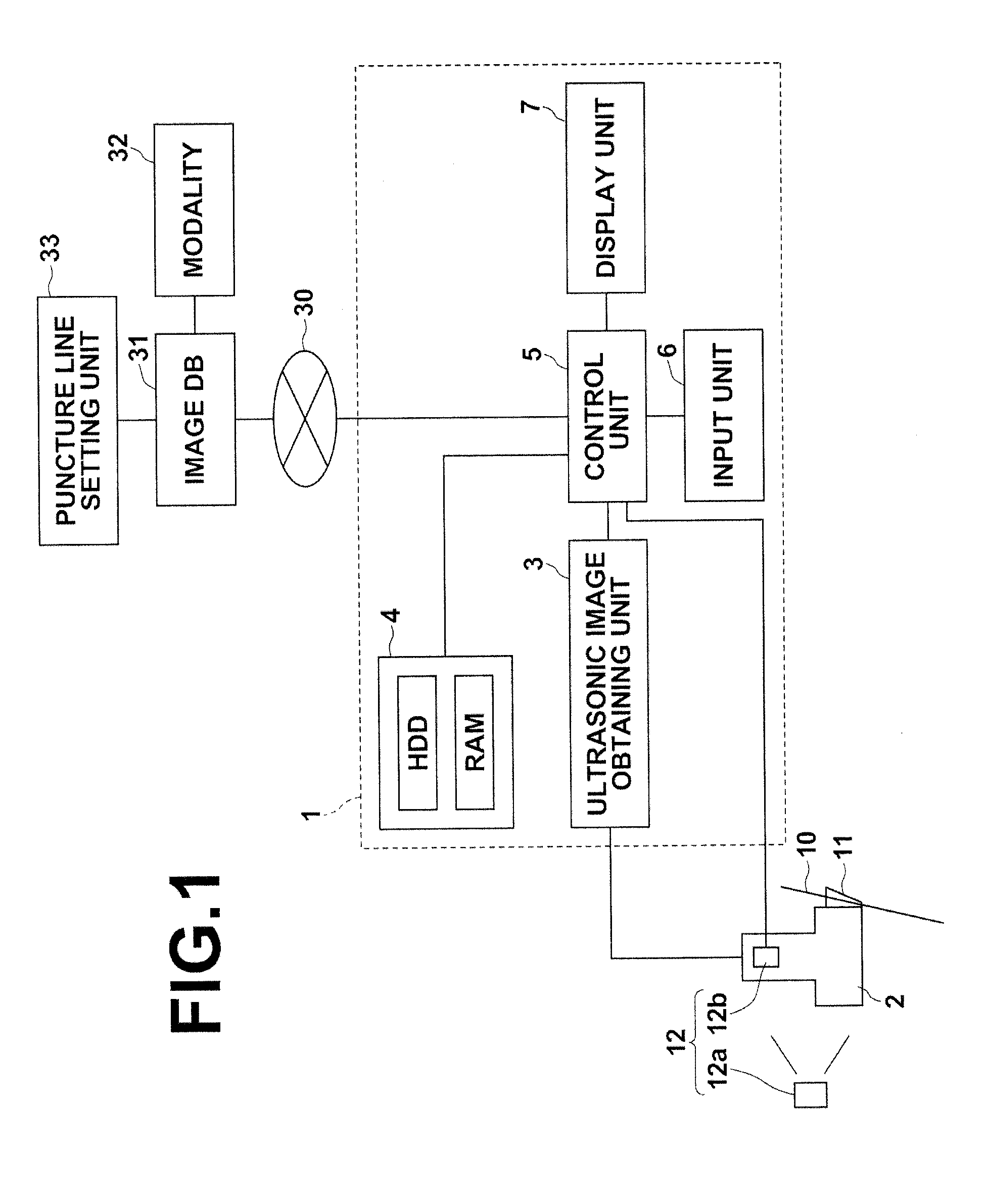
[0049]Hereinafter, embodiments of the present invention will be described with reference to the accompanying drawings. FIG. 1 is a schematic block diagram of an ultrasonic diagnostic system to which a medical image display apparatus according to a first embodiment of the present invention is applied, illustrating a configuration thereof. As illustrated in FIG. 1, the ultrasonic diagnostic system 1 according to the first embodiment includes an ultrasonic probe 2, an ultrasonic image obtaining unit 3, a storage unit 4, a control unit 5, an input unit 6, and a display unit 7. Note that the ultrasonic image obtaining unit 3 and the control unit 5 constitute the medical image display apparatus of the present invention.

[0050]The ultrasonic probe 2 transmits ultrasonic waves toward a diagnostic region of a subject and receives ultrasonic waves reflected at the inside the body of the subject. The ultrasonic probe 2 of the present embodiment includes a plurality of ultrasonic transducers, wh...


PUM


Abstract

Scanning a subject with an ultrasonic probe and obtaining an ultrasonic image of the subject. Obtaining a cross-sectional image of a cross-section of a three-dimensional image corresponding to the ultrasonic image from the three-dimensional image, the three-dimensional image including a puncture line set for a puncture needle and a superimposed columnar index having a central axis line on the puncture line and opacity which is reduced with the distance from the central axis line. Displaying the ultrasonic image and the cross-sectional image. In this case, the thickness, opacity, and cross-sectional shape of the index displayed on the cross-sectional image vary according to the positional relationship between the scan plane of the ultrasonic probe and the cross-section in which the puncture line is set.

Description

CROSS-REFERENCE TO RELATED APPLICATIONS[0001]The present application claims priority under 35 U.S.C. §119 to Japanese Patent Application No 2014-052887 filed on Mar. 17, 2014. The above application is hereby expressly incorporated by reference, in its entirety, into the present application.BACKGROUND OF THE INVENTION[0002]1. Field of the Invention[0003]The present invention relates to a medical image display apparatus, method, and program capable of supporting an operation of an ultrasonic probe in an ultrasonic diagnostic system that obtains an ultrasonic image of a subject.[0004]2. Description of the Related Art[0005]Heretofore, ultrasonic diagnostic systems using ultrasonic images have been put into practical use in medicine. Generally, such type of an ultrasonic diagnostic system includes an ultrasonic probe and a main body connected to the ultrasonic probe, and generates an ultrasonic image by transmitting an ultrasonic wave from the ultrasonic probe toward a subject to scan th...

Claims


Application Information

Patent Timeline
Patent Type & Authority Applications(United States)
IPC IPC(8): A61B8/08A61B8/00
CPCA61B8/0841A61B8/483A61B8/54A61B8/466A61B8/463A61B8/523A61B6/5247A61B8/0833A61B8/5261G06T19/00A61B2017/3413G06T2210/41G06T2219/008A61B6/5223A61B8/4254A61B2034/107
Inventor MASUMOTO, JUN
Owner FUJIFILM CORP
Why Eureka
Try Eureka