Method of manufacturing thermal module with enhanced assembling structure

a technology of assembling structure and thermal modules, which is applied in the direction of indirect heat exchangers, semiconductor/solid-state device details, lighting and heating apparatus, etc., can solve the problems of high manufacturing cost, inability to fasten a heat pipe to a heat-dissipation base, and not all heat-dissipation elements can be assembled to one another with screws, so as to improve the tightness of fittings, enhance assembling strength, and save the effect of assembling hea

Active Publication Date: 2015-09-17
ASIA VITAL COMPONENTS SHENZHEN CO LTD
View PDF8 Cites 10 Cited by
  • Summary
  • Abstract
  • Description
  • Claims
  • Application Information

AI Technical Summary

Benefits of technology

[0013]According to the present invention, the first and the second extended arm are formed at junctions between the opening of the receiving recess and the first side of the base, and the two rows of alternating elevated and sunken areas are formed on the wall surfaces located between the opening and the first and the second extended arm. After the heat pipe is set in the receiving recess on the base, a downward force is applied to deform the first and the second extended arm for them to press against and accordingly hold down the heat pipe, such that the top surface of the heat pipe is flush with the first side of the base. Meanwhile, the bottom surface of the heat pipe under the downward force is deformed at areas that are in contact with the two rows of

Problems solved by technology

For example, the heat generated by the CPU during operation thereof is high enough to burn out the whole CPU.
Thus, it is always a very important issue as how to properly provide a heat dissipation device for various chips.
Therefore, the forming of the conventional thermal modules involves complicated processing procedures and accordingly requires high manufacturing cost.
However, not all the heat-dissipation elements can be assembled to one another with the screws.
For example, the screws can be used to fasten heat radiation fins to a heat-dissipation base, but could not be used to fasten a heat pipe to a heat-dissipation base.
While this assembling way overcomes the problem in welding and screwing the heat-dissipation elements to form the therma

Method used


Image

  • Method of manufacturing thermal module with enhanced assembling structure
  • Method of manufacturing thermal module with enhanced assembling structure
  • Method of manufacturing thermal module with enhanced assembling structure

Examples


Embodiment Construction

[0025]The present invention will now be described with some preferred embodiments thereof and with reference to the accompanying drawings. For the purpose of easy to understand, elements that are the same in the preferred embodiments are denoted by the same reference numerals.

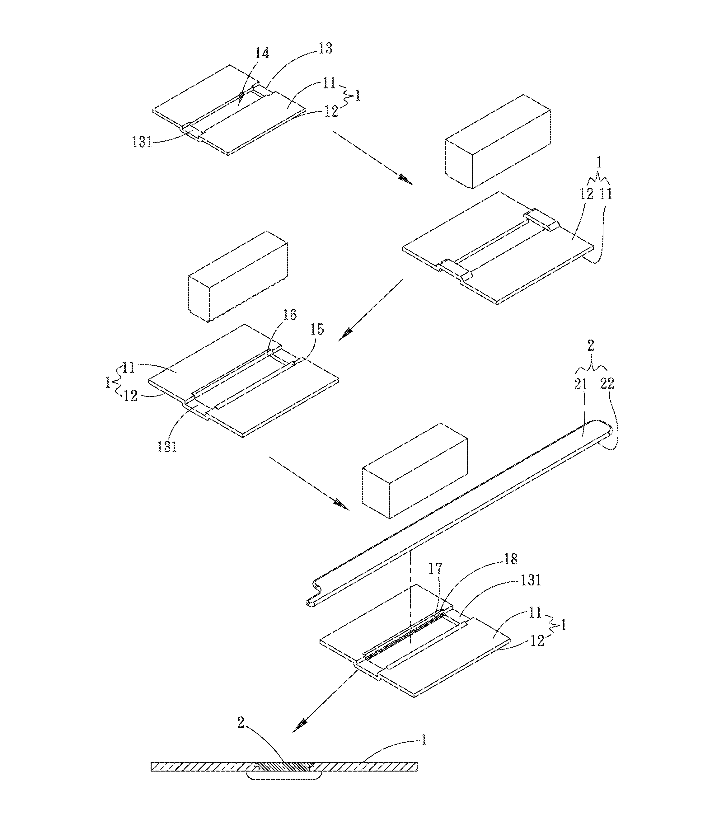
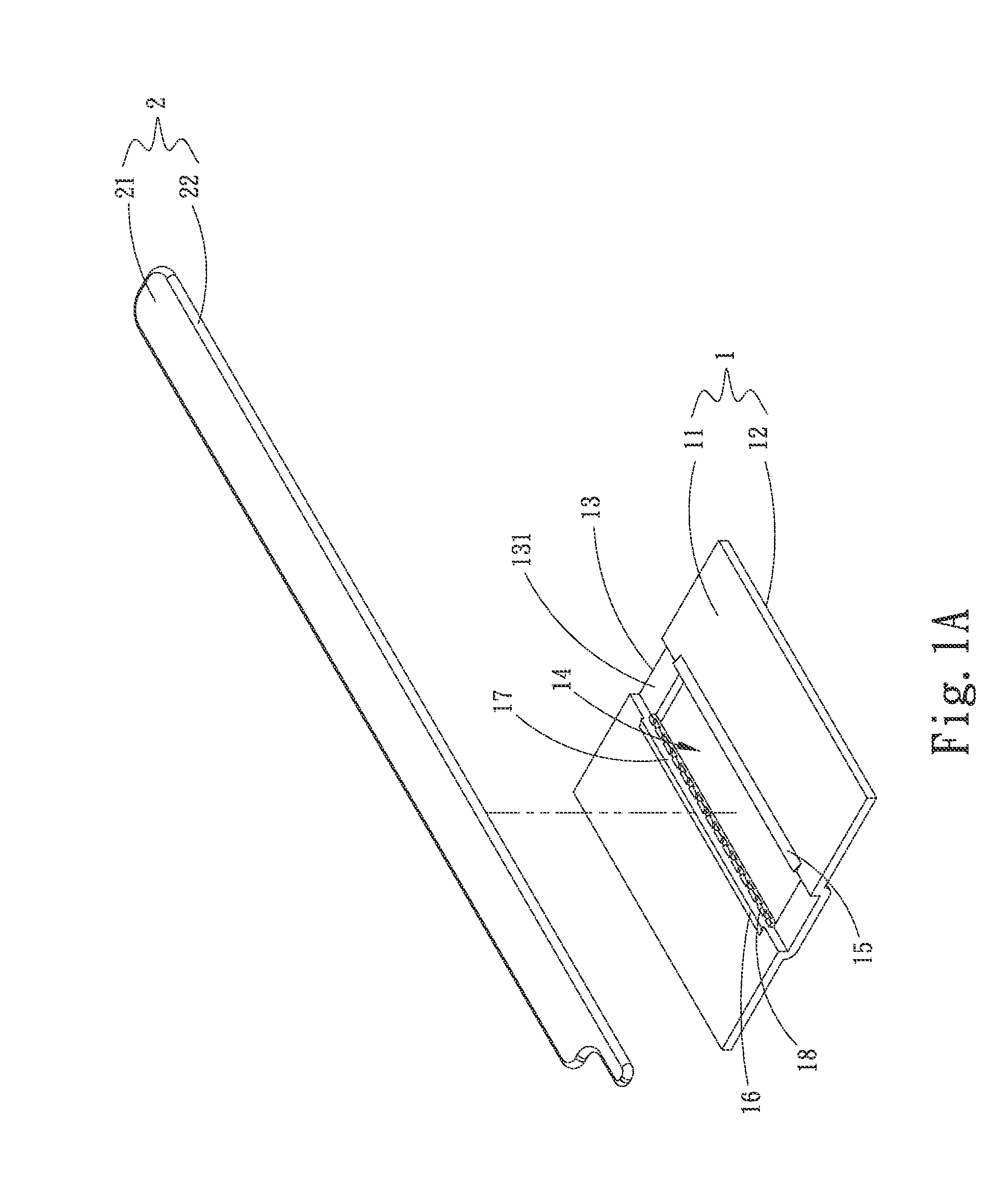
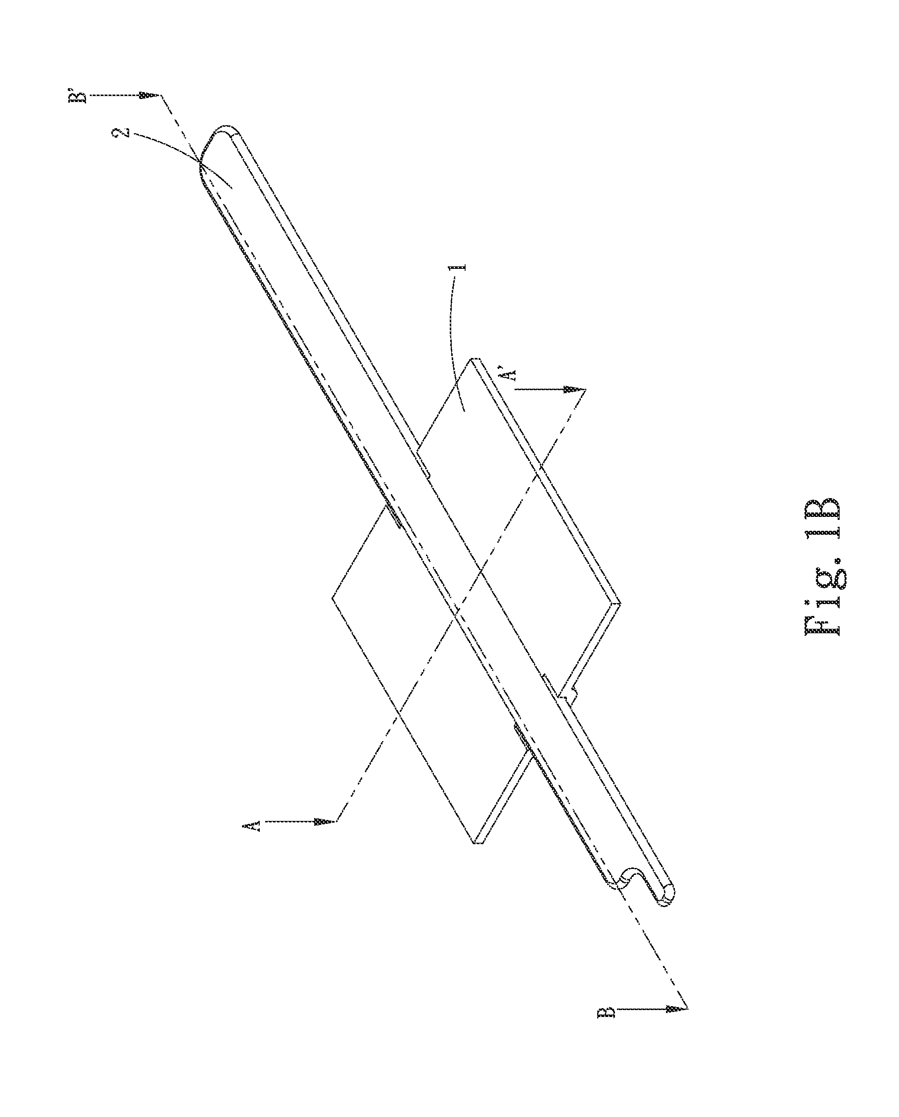
[0026]Please refer to FIGS. 1A and 1B that are exploded and assembled perspective views, respectively, of a thermal module with enhanced assembling structure according to a first embodiment of the present invention. For the purpose of conciseness and clarity, the present invention is also briefly referred to as “the thermal module” herein. As shown, in the first embodiment, the thermal module includes a base 1 and a heat pipe 2. The base 1 has a top defined as a first side 11 and a bottom defined as a second side 12, and has a longitudinal receiving recess 13 formed at a middle area thereof. The receiving recess 13 has a middle portion formed into an opening 14 and two end portions respectively forming a suppor...


PUM

PropertyMeasurementUnit
Areaaaaaaaaaaa
Strengthaaaaaaaaaa

Abstract

A thermal module with enhanced assembling structure includes a base and a heat pipe. The base is formed on a middle portion with a longitudinal receiving recess, which has two end portions forming two supporting portions and a middle portion formed into an opening. A first and a second extended arm are formed at junctions between the receiving recess and two longitudinal sides of the opening. Wall surfaces of the first and second extended arms adjacent to the longitudinal sides of the opening are formed with alternating elevated and sunken areas. The heat pipe is held down in the receiving recess by the first and second extended arms to fitly engage with the elevated and sunken areas. Therefore, there is an increased fitting tightness between the heat pipe and the base to ensure enhanced assembling strength of the thermal module and reduce the manufacturing cost thereof.

Description

FIELD OF THE INVENTION[0001]The present invention relates to a thermal module with enhanced assembling structure, and more particularly to a thermal module having increased assembling strength and reduced manufacturing cost.BACKGROUND OF THE INVENTION[0002]The progress in the electronic technology enables various chips, such as the central processing unit (CPU), to have gradually reduced volume. Meanwhile, for the chips to process more data, the number of electronic components provided on the presently available chips is several times higher than that on the conventional chips of the same volume. When the number of electronic components on the chips increases, the heat generated by the electronic components during operation thereof also increases. For example, the heat generated by the CPU during operation thereof is high enough to burn out the whole CPU. Thus, it is always a very important issue as how to properly provide a heat dissipation device for various chips.[0003]The curren...

Claims


Application Information

Patent Timeline
IPC IPC(8): B23P15/26
CPCB23P15/26B23P2700/10F28D15/0233F28D15/0275H01L23/427F28F2275/14H01L2924/0002Y10T29/4935H01L2924/00F28D1/00H01L23/00
Inventor LIN, SHENG-HUANGLIN, KUO-SHENG
Owner ASIA VITAL COMPONENTS SHENZHEN CO LTD
Why Eureka
Try Eureka