
Bioreactor, reactor bag for same and stirrer for circulating contents of said bag

a technology for reactor bags and bioreactors, which is applied in specific use bioreactors/fermenters, biomass after-treatment, transportation and packaging, etc. it can solve the problems of unsolved definitively solved problems such as contamination risk, stirrers located in the interior of the reactor container, etc., and achieve the effect of reducing the shear force affecting the cells

Active Publication Date: 2015-09-17
SARTORIUS STEDIM BIOTECH GMBH
View PDF0 Cites 5 Cited by
  • Summary
  • Abstract
  • Description
  • Claims
  • Application Information

AI Technical Summary

Benefits of technology

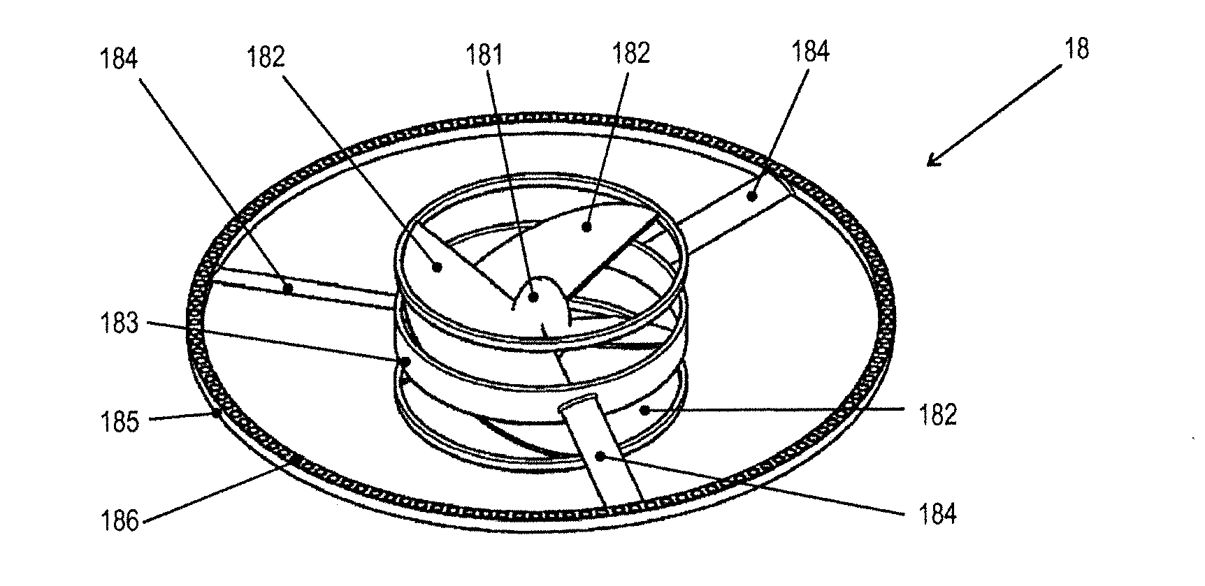
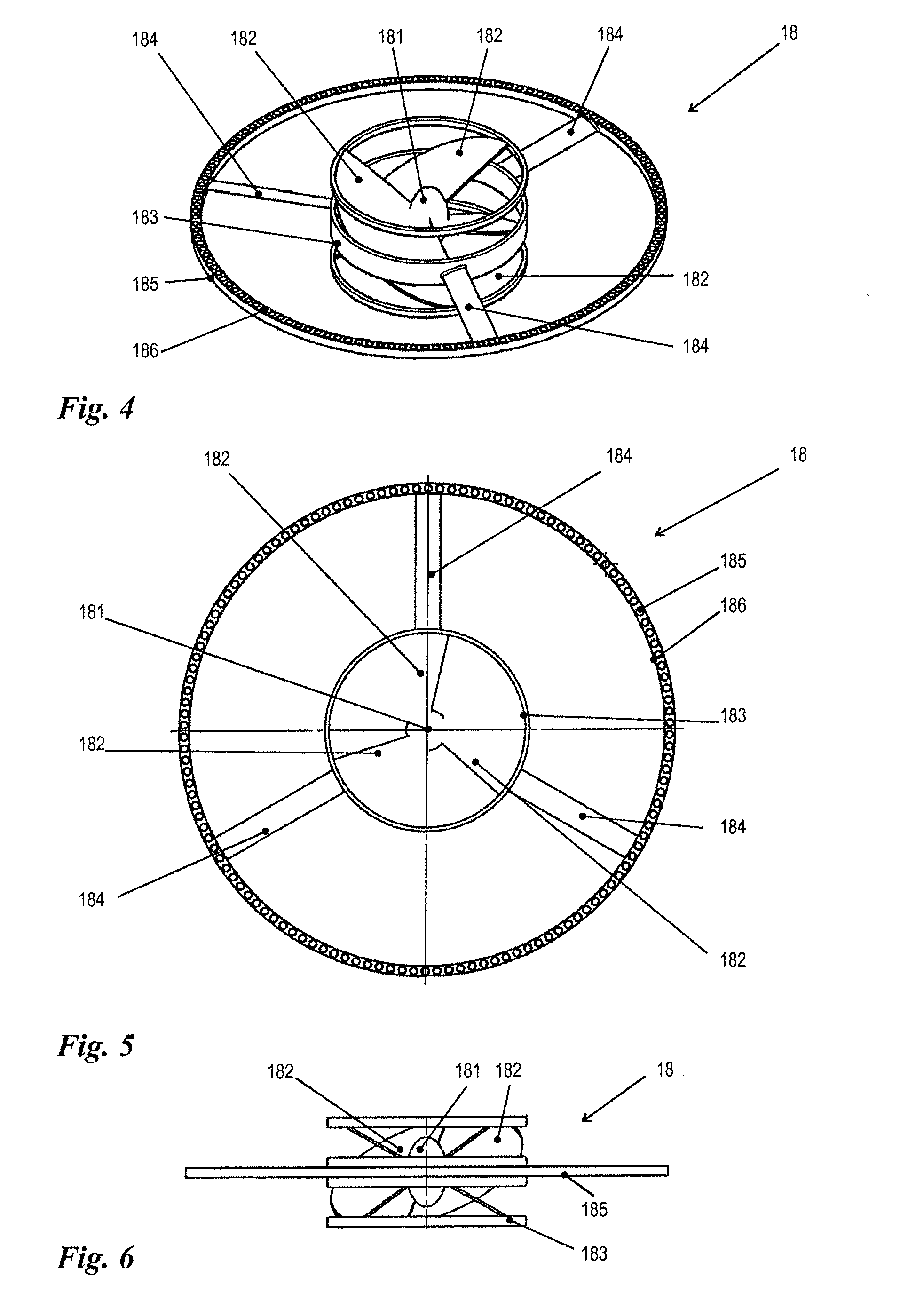
This patent describes a design for a stirrer used in bioreactors that reduces friction and allows for a more efficient mixing of reactor contents. The design includes a profile ring with a ridge that guides the rotor in both the axial and radial directions. The ridge also forms a surface for mounting an electric coil arrangement, which generates the magnetic field. This design helps to minimize the distance between the coil and the internal magnet of the stirrer, leading to a more powerful interaction between the two and requiring less powerful magnets and currents. The rotor also has a central body and at least three spokes that serve to effect the mixing process and minimize damage to the cells in cell cultures.

Problems solved by technology

One difficulty is causing the stirrers located in the interior of the reactor container to move in the desired stirring direction by means of drive mechanisms usually arranged outside of the reactor container.
However, the problem of appropriately circulating the contents of the bag has not been definitively solved.
In particular, versions with stirrer shafts that penetrate the bag wall are regarded as disadvantageous as this increases the risk of contamination, considerably increases the amount of space required for storage and, because of the necessity of providing a sealed penetration point for the shaft, renders the manufacture of the bags more complicated and expensive.
On the one hand, it is limited in that the position of the stirrer is restricted to the bottom region of the reactor bag, which can be expected to result in insufficient mixing of the reactor contents in tall bioreactors.
This means that during transport, the stirrer can easily fall out of its bearing and damage the bag walls with its sharp-edged paddles.

Method used


Image

  • Bioreactor, reactor bag for same and stirrer for circulating contents of said bag
  • Bioreactor, reactor bag for same and stirrer for circulating contents of said bag
  • Bioreactor, reactor bag for same and stirrer for circulating contents of said bag

Examples


Embodiment Construction

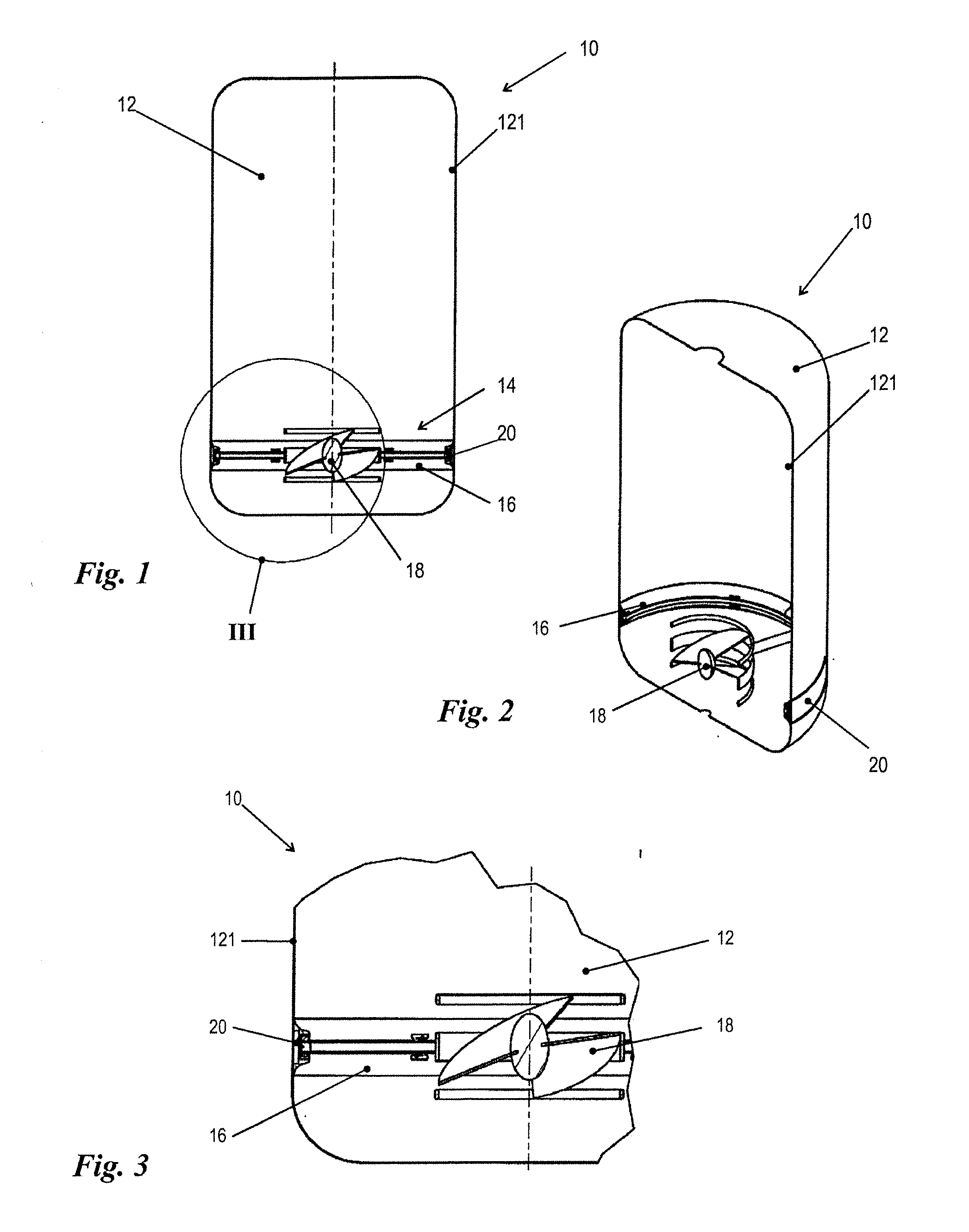
[0049]FIGS. 1 to 14 illustrate as an example a preferred embodiment of the invention and will be discussed together, unless specific reference is made to a particular figure. FIG. 15 and show, purely schematically and as an example, two possible coil / magnet configurations to implement the motorized drive of a stirrer arrangement in accordance with the invention, especially a stirrer arrangement in accordance with FIGS. 1 to 14. Identical reference numbers in the figures indicate identical or analogous elements.

[0050]FIGS. 1 to 3 show highly schematic views of a bioreactor that has a reactor bag 12 and a stirrer arrangement 14. The reactor bag 12 has a predominantly flexible bag wall 121 that is made rigid only in the area of the stirrer arrangement 14 by the latter's profile ring 16, which is made of a rigid, non-magnetic material, e.g. plastic. Preferably, the bag wall 121 is interrupted in the area of the stirrer arrangement 14 and is at least partially replaced by the profile rin...


PUM


Abstract

A bioreactor has a reactor bag (12) with a predominantly flexible bag wall (121) that has a rigid bearing area. A stirrer arrangement (14) is in the bearing area and includes rigid profile ring (16) made of a non-magnetic material and fixed in the bearing area. The stirrer arrangement (14) also includes a shaftless stirrer (18) rotatably engaged with the profile ring (16) and having parts that are permanently magnetic. An electric coil arrangement (20) is outside the reactor bag (12) and can produce a rotating magnetic field that interacts with the permanent-magnetic areas of the stirrer (18) to produce a torque that rotates the stirrer (18) and circulates the contents of the bag (12).

Description

BACKGROUND[0001]1. Field of the Invention[0002]The invention relates to a bioreactor, comprising[0003]a reactor bag with a predominantly flexible bag wall which has a rigidly formed bearing area for housing a stirrer serving to circulate contents of the bag,[0004]a shaftless stirrer, parts of which are permanently magnetic, housed inside the bag in the bearing area, and[0005]a coil arrangement positioned outside the reactor bag with which coil arrangement a rotating magnetic field can be produced, which magnetic field interacts, in a manner exerting a torque on the stirrer, with the permanent-magnetic areas thereof.[0006]2. Description of the Related Art[0007]The invention further relates to a reactor bag for a bioreactor, comprising a predominantly flexible bag wall which has a rigidly formed bearing area for housing a shaftless stirrer serving to circulate the contents of the bag, at least parts of the stirrer being permanently magnetic.[0008]Finally, the invention relates to a st...

Claims


Application Information

Patent Timeline
IPC IPC(8): C12M1/06C12M1/00
CPCC12M23/14C12M27/02C12M23/28B01F33/453B01F35/513
Inventor ZEUCH, STEFANREGEN, THOMASGRELLER, GERHARDREIF, OSCAR-WERNER
Owner SARTORIUS STEDIM BIOTECH GMBH
Learn More