Light to Frequency Converter Optical Sensor with Electronic Bias and Adjustable Gain

a frequency converter and optical sensor technology, applied in the field of optical sensors, can solve the problems of biasing light sources, low grayscale photonic resolution, and inability to measure intensity,

Inactive Publication Date: 2015-09-17
SPECTRAL SENSORS
View PDF0 Cites 5 Cited by
  • Summary
  • Abstract
  • Description
  • Claims
  • Application Information

AI Technical Summary

Benefits of technology

[0018]It is yet another object of the present invention to provide an improved optical sensor and improved optical sensing m

Problems solved by technology

Unfortunately, this method produces low grayscale photonic resolution when light intensities are low because the intensity range may only produce a limited number of pulses.
Another disadvantage of counting the output pulses is that there i

Method used


Image

  • Light to Frequency Converter Optical Sensor with Electronic Bias and Adjustable Gain
  • Light to Frequency Converter Optical Sensor with Electronic Bias and Adjustable Gain
  • Light to Frequency Converter Optical Sensor with Electronic Bias and Adjustable Gain

Examples


Embodiment Construction

[0025]The present invention will be described in greater detail with reference to certain preferred and alternative embodiments of systems and methods in accordance with the present invention. As described below, refinements and substitutions of the various embodiments are possible based on the principles and teachings herein.

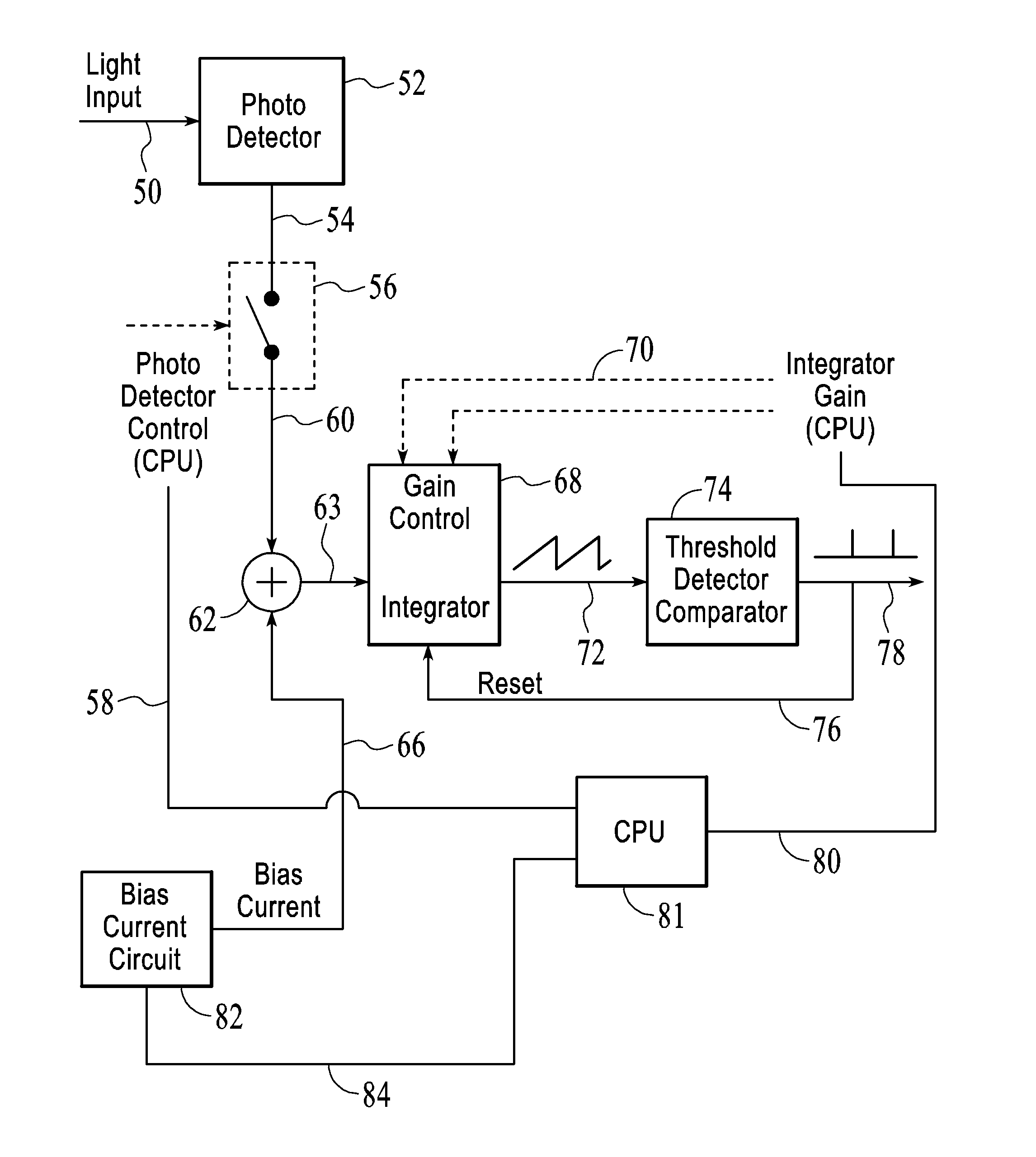
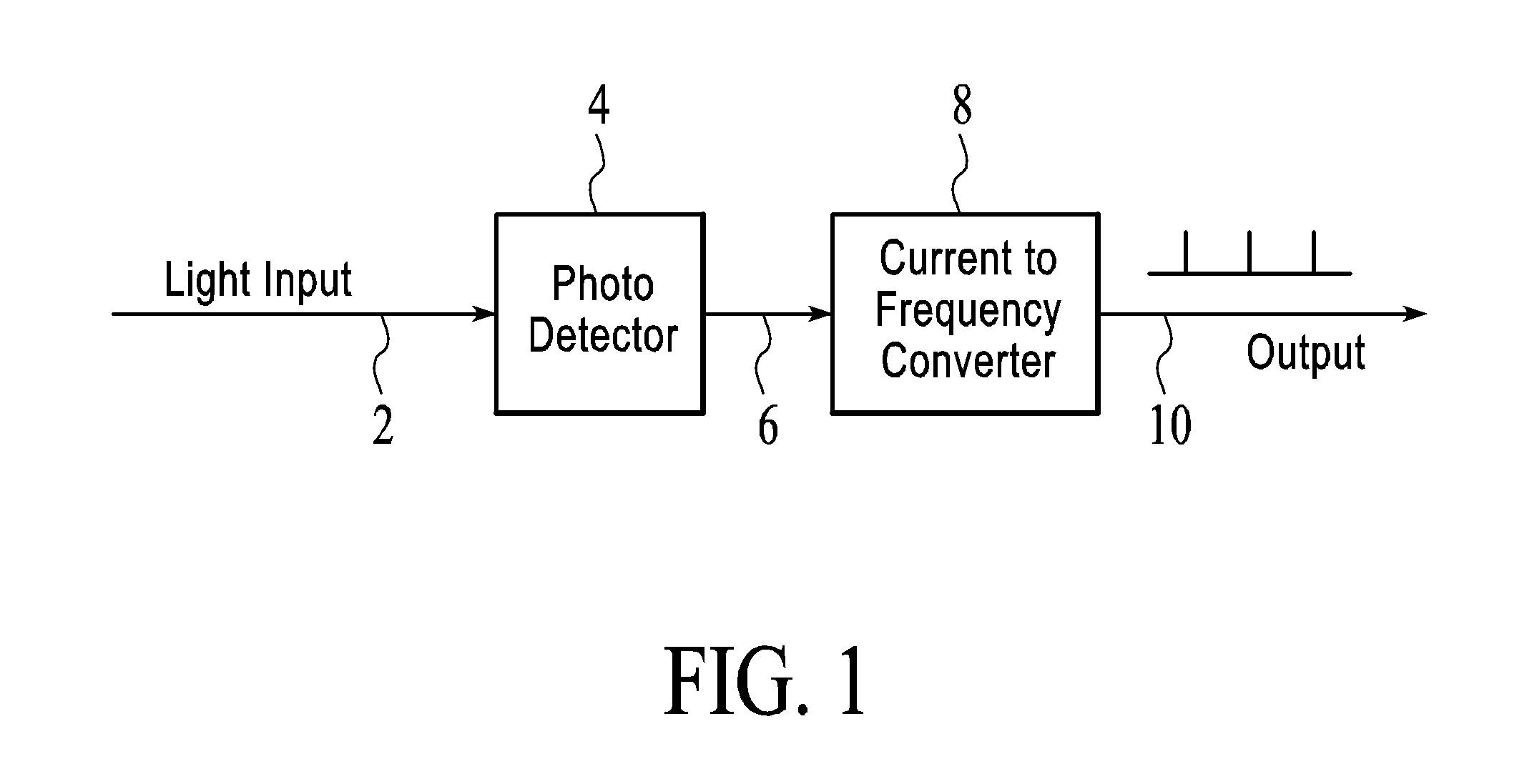
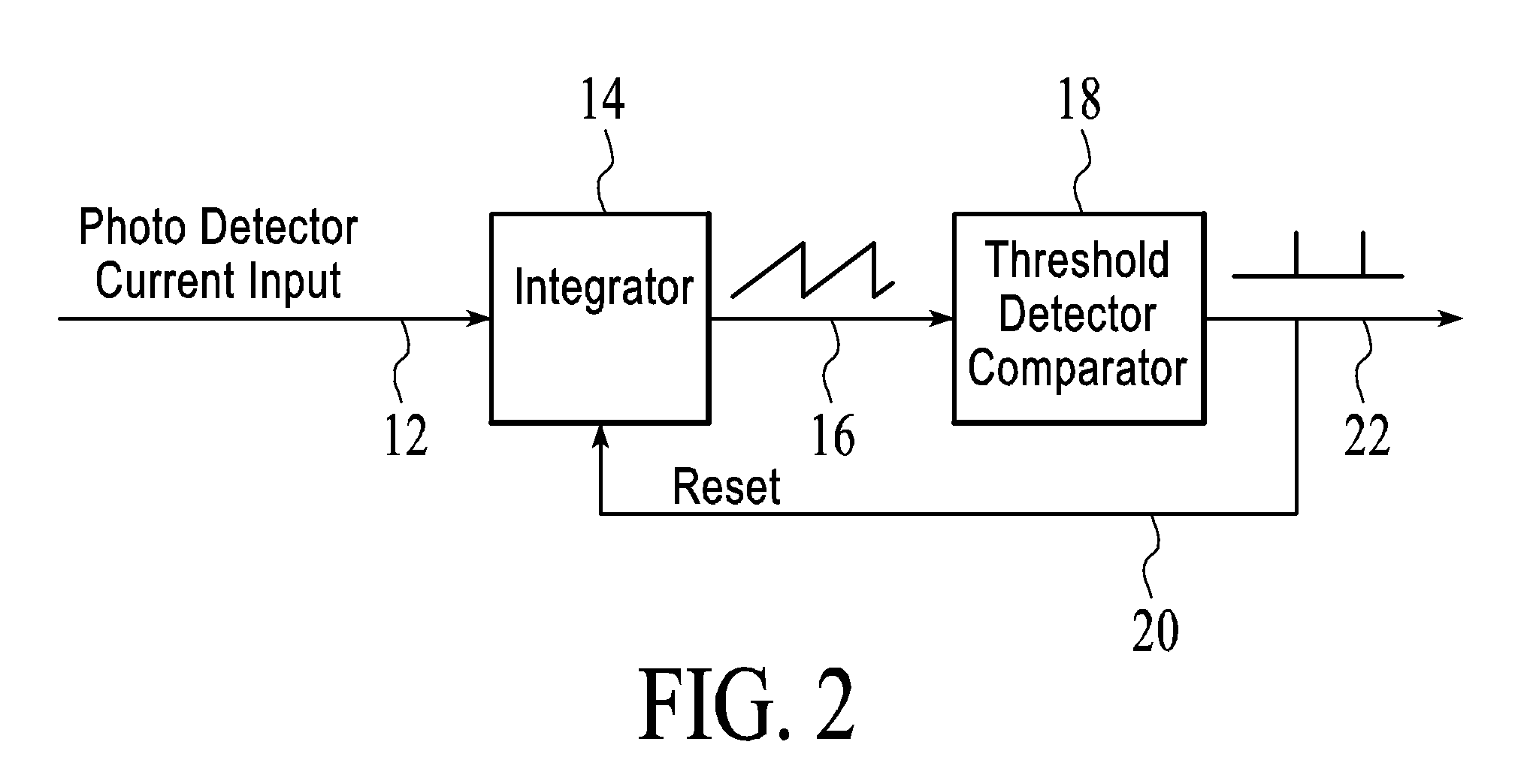
[0026]As previously above and in the Referenced Patent Documents, light bias can desirably be utilized with light to frequency converters. When utilizing light bias to extend the range of light intensities that can be measured with light to frequency converters, however, it typically is necessary to measure the intensity of the light bias. It also typically is necessary to maintain a light bias that is stable during the measurement process or to independently monitor the bias intensity while measuring the unknown light intensity. This can be achieved with an additional sensor independently measuring bias or it can be achieved by making two measurements in rapid...


PUM


Abstract

An improved light to frequency converter optical sensor and method using electronic bias. Adjustable gain also may be provided. A summing circuit sums electrical current from a photo detector and electrical current from a bias current circuit and provides the summed current to an integrator. A threshold detector comparator circuit has an input coupled to the output of the integrator and an output providing a series of pulses. The series of pulses has a frequency based on the light received by the photo detector and the electrical current from the bias current circuit.

Description

[0001]This application claims priority on U.S. Provisional App. Ser. No. 61852136, filed Mar. 15, 2013.FIELD OF THE INVENTION[0002]The present invention relates to optical sensors, and more particularly to a light to frequency converter optical sensor-based systems and methods utilizing electronic bias and adjustable gain in such systems.BACKGROUND OF THE INVENTION[0003]Light to frequency converters (LFCs) are used to measure the intensity of light. Generally, such optical sensors consist of an electronic circuit having a photo detector and a current (or voltage) to frequency converter. FIG. 1 is a block diagram of a typical light to frequency converter. The photo detector produces a voltage or a current. The current (or voltage) to frequency converter produces a frequency that generally is proportional to the light intensity detected or received by the photo detector. As illustrated in FIG. 1, light input 2 couples received light to photo detector 4, which is coupled via line 6 to ...

Claims


Application Information

Patent Timeline
IPC IPC(8): G01J1/44
CPCH03M1/18G01J1/44H03M1/60
Inventor JUNG, WAYNE D
Owner SPECTRAL SENSORS
Why Eureka
Try Eureka