Bone conduction speaker unit

a conduction speaker and bone technology, applied in the direction of transducer details, electrical transducers, electrical apparatus, etc., can solve the problems of increasing manufacturing costs, unable to avoid sound leakage generation, and insufficient degree, so as to reduce manufacturing costs and minimize sound leakage , the effect of simple construction

Inactive Publication Date: 2015-09-17
TEMCO JAPAN
View PDF4 Cites 77 Cited by
  • Summary
  • Abstract
  • Description
  • Claims
  • Application Information

AI Technical Summary

Benefits of technology

[0014]The present invention is as described above, providing an advantage that, at the time of the bone conduction speaker unit being not in use, when no pressing force is applied to the elastic cover, a gap is always held between the bottom face of the contact and the top face of the elastic plate, or between the bottom face of the thick-wall part and the top face of the plate yoke, thereby it being reliably prevented that a vibration is unnecessarily transmitted to the elastic cover to cause generation of a voice vibration, resulting in sound leakage, and when in use, the elastic cover is pressed against a side face of the head, or the like, ...

Problems solved by technology

However, in that case, at the time of non-calling, in other words, also when the contact is not pressed against a side face of the head, the contact is vibrated together with bone conduction speaker being operated, thereby a voice vibration (an air conduction sound) being generated, and thus generation of a certain degree of sound leakage cannot be avoided, presenting a pro...

Method used


Image

  • Bone conduction speaker unit
  • Bone conduction speaker unit
  • Bone conduction speaker unit

Examples


first embodiment

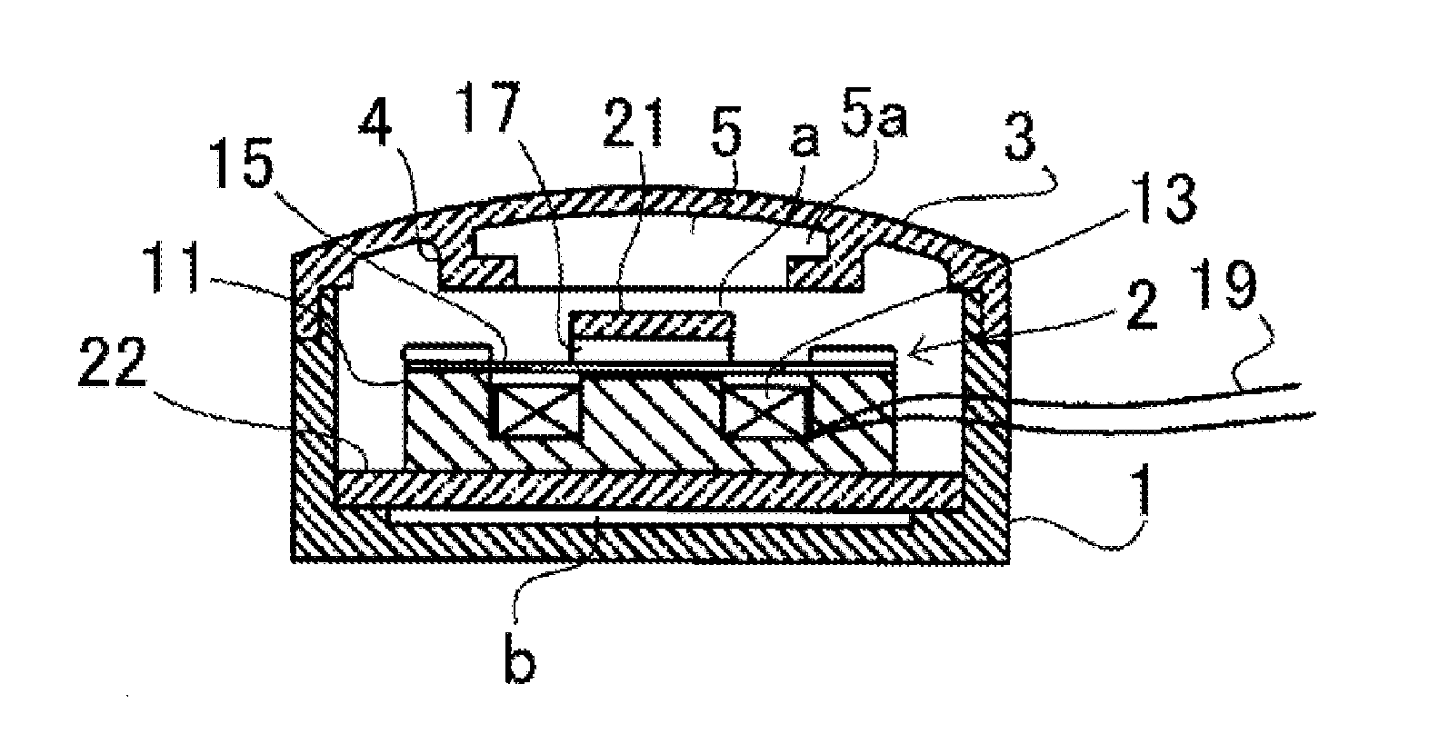
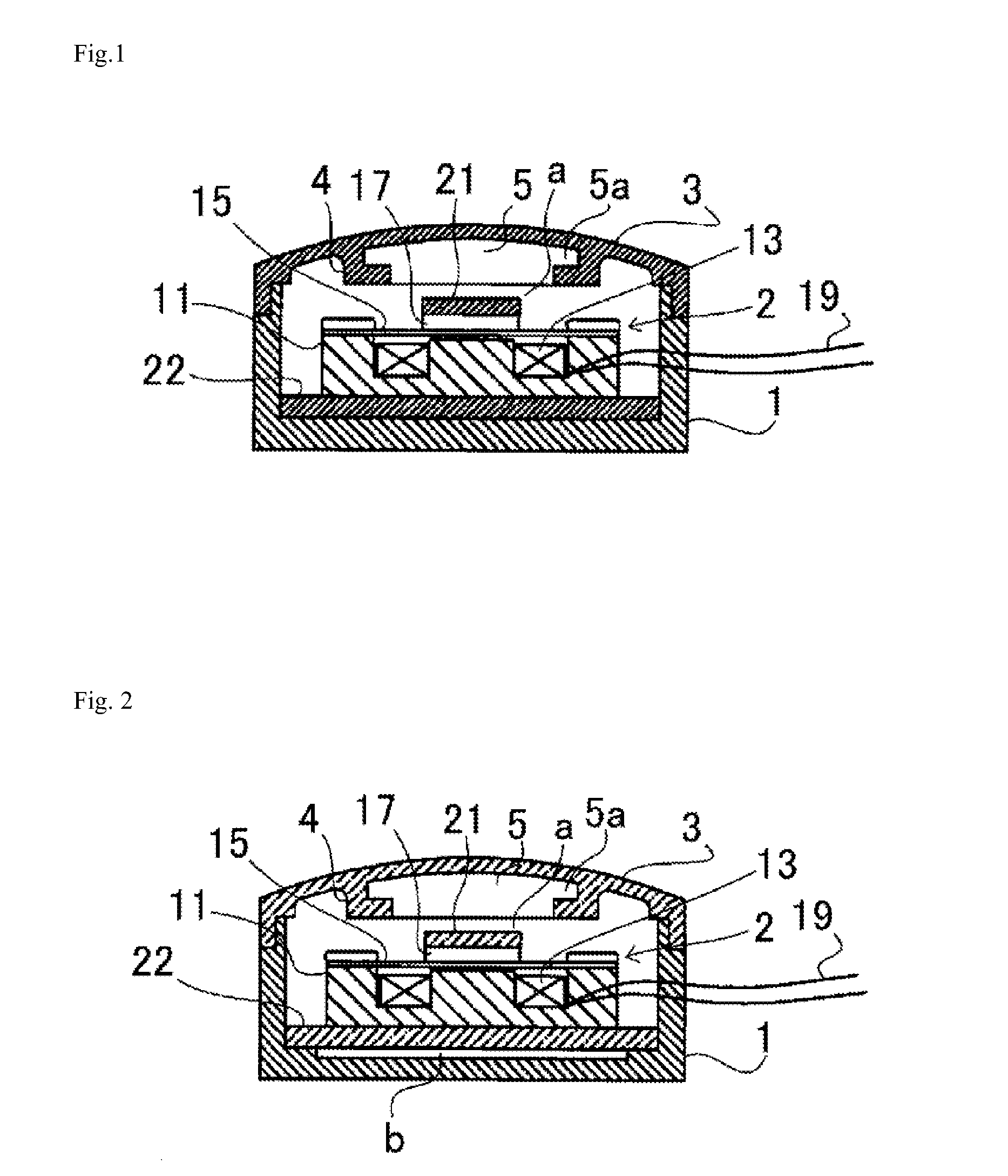
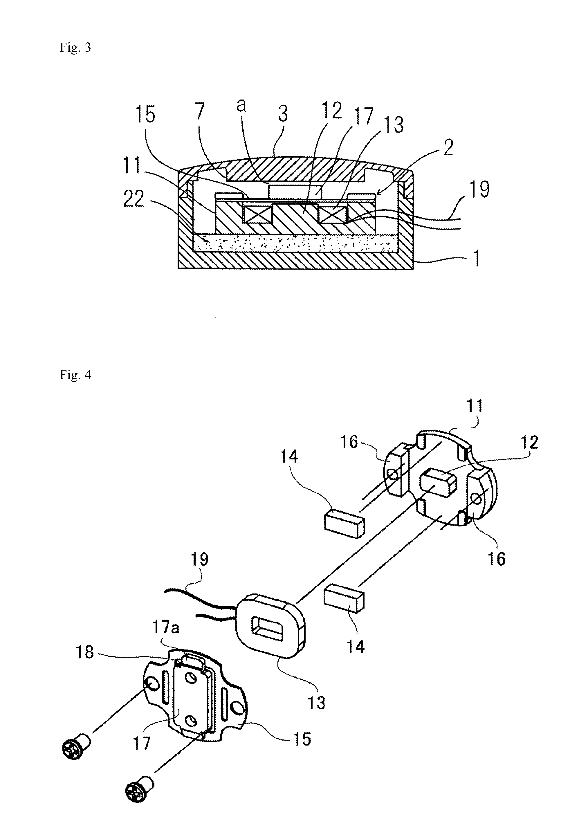
[0020]Hereinbelow, embodiments of the present invention will be explained with reference to the accompanying drawings. FIG. 1 is a longitudinal sectional view of a bone conduction speaker unit according to the present invention, and as shown in the same figure, the bone conduction speaker unit in accordance with the present invention includes a housing 1; a bone conduction speaker main body 2 incorporated in the housing 1; and an elastic cover 3 mounted on the housing 1.

[0021]The bone conduction speaker main body 2 is configured as shown in, for example, FIG. 4, with a voice coil 13 being disposed so as to surround a center pole 12 provided in the central portion of a yoke 11, a pair of bar-like magnets 14, 14 being fixed to both sides of the voice coil 13, and a diaphragm 15 being disposed so as to cover the voice coil 13 and the magnets 14, 14. The diaphragm 15 is fixed with both end parts thereof being screw-fastened to the top face of side walls 16 which are erected on both end ...

second embodiment

[0033]In this second embodiment, the above contact 5 is not used, and instead of it, a thick-wall part 7, the bottom face of which is flat, is integrally formed on the internal top face of the elastic cover 3, and upon the elastic cover 3 being mounted on the housing 1, a gap “a” is held between the bottom face of the thick-wall part 7 and the top face of the plate yoke 17 of the bone conduction speaker main body 2.

[0034]Also with this bone conduction speaker unit according to the second embodiment, at the time of non-calling, when a pressing force is not applied to the elastic cover 3, the plate yoke 17 is separated from the thick-wall part 7 by a distance of the gap “a”, and therefore, even if the plate yoke 17 is vibrated, the vibration will not be transmitted to the thick-wall part 7, in other words, the elastic cover 3, thereby an unintended sound being prevented from being generated. Further, at the time of calling, if the elastic cover 3 is pushed in toward the inside, the bo...


PUM


Abstract

Problem: To provide a bone conduction speaker unit which can sufficiently prevent generation of sound leakage at the time of non-calling, and can be easily incorporated in a main body casing of mobile phones, and the like.
Solution: A bone conduction speaker unit, being configured by incorporating a bone conduction speaker main body 2 in a housing 1, wherein an elastic plate 21 is fixed on a top face of a plate yoke 17 of the bone conduction speaker main body 2; an elastic base 22 is disposed on a rear face of a yoke 11; and an elastic cover 3 for holding a contact 5 which, upon a pressing force having been applied thereto in use, is abutted against the plate yoke 17 through the elastic plate 21 is loaded on the housing 1 with a gap “a” being held between a bottom face of the contact 5 and a top face of the elastic plate 21.

Description

TECHNICAL FIELD[0001]The present invention relates to a bone conduction speaker unit, and more particularly, to a bone conduction speaker unit which, upon being incorporated in a mobile phone, or the like, will not present a problem of sound leakage.BACKGROUND ART[0002]The bone conduction speaker unit converts a voice signal into a vibration to transmit it to the skull, and the like, being compact and lightweight and capable of being used even under noise, whereby, in recent years, it has been widely used with communication apparatuses, such as a mobile phone, and the like.[0003]In order to transmit a vibration of a diaphragm constituting the bone conduction speaker to the skull, a contact which is abutted against a side face of the head is fixed to the diaphragm, and for efficient transmission of the vibration of the diaphragm to this contact, the contact is fixed to the diaphragm (the plate yoke) in plane contact over a wide area (WO2005 / 069586A1, and the like). However, in that c...

Claims


Application Information

Patent Timeline
IPC IPC(8): H04R1/46
CPCH04R2499/11H04R1/46H04R1/025H04R9/06H04R2460/13H04R9/066
Inventor FUKUDA, MIKIO
Owner TEMCO JAPAN
Why Eureka
Try Eureka