
Robot and method for milking a cow by this robot

a robot and milking machine technology, applied in the field of robots, can solve the problems of manual placement of milking cups, low production rate of this known system, and laborious milking of cows, and achieve the effect of saving spa

Active Publication Date: 2015-09-24
TECH HLDG
View PDF1 Cites 8 Cited by
  • Summary
  • Abstract
  • Description
  • Claims
  • Application Information

AI Technical Summary

Benefits of technology

The patent describes a device that allows a person to easily place milking cups on a cow's teats. The device includes a gripper that is mounted on a support at the end of an arm. The gripper can be extended from the support and moved from behind the cow to the area between the cow's hind-legs. The gripper can also be swivelled to allow for easier placement of the milking cups on the cow's teats. The technical effect of this device is to save space and facilitate the placement of milking cups on the cow's teats.

Problems solved by technology

The production rate of this known system is, however, relatively low in view of the fact that it is only possible to milk one cow at a time.
In this known system a disadvantage is, however, that the milking cups are placed manually.
Due thereto in this system with a cow's rotor, the milking of cows is still quite laborious.

Method used


Image

  • Robot and method for milking a cow by this robot
  • Robot and method for milking a cow by this robot
  • Robot and method for milking a cow by this robot

Examples


Embodiment Construction

[0028]Wherever in the figures the same reference numerals are applied these numerals refer to the same parts.

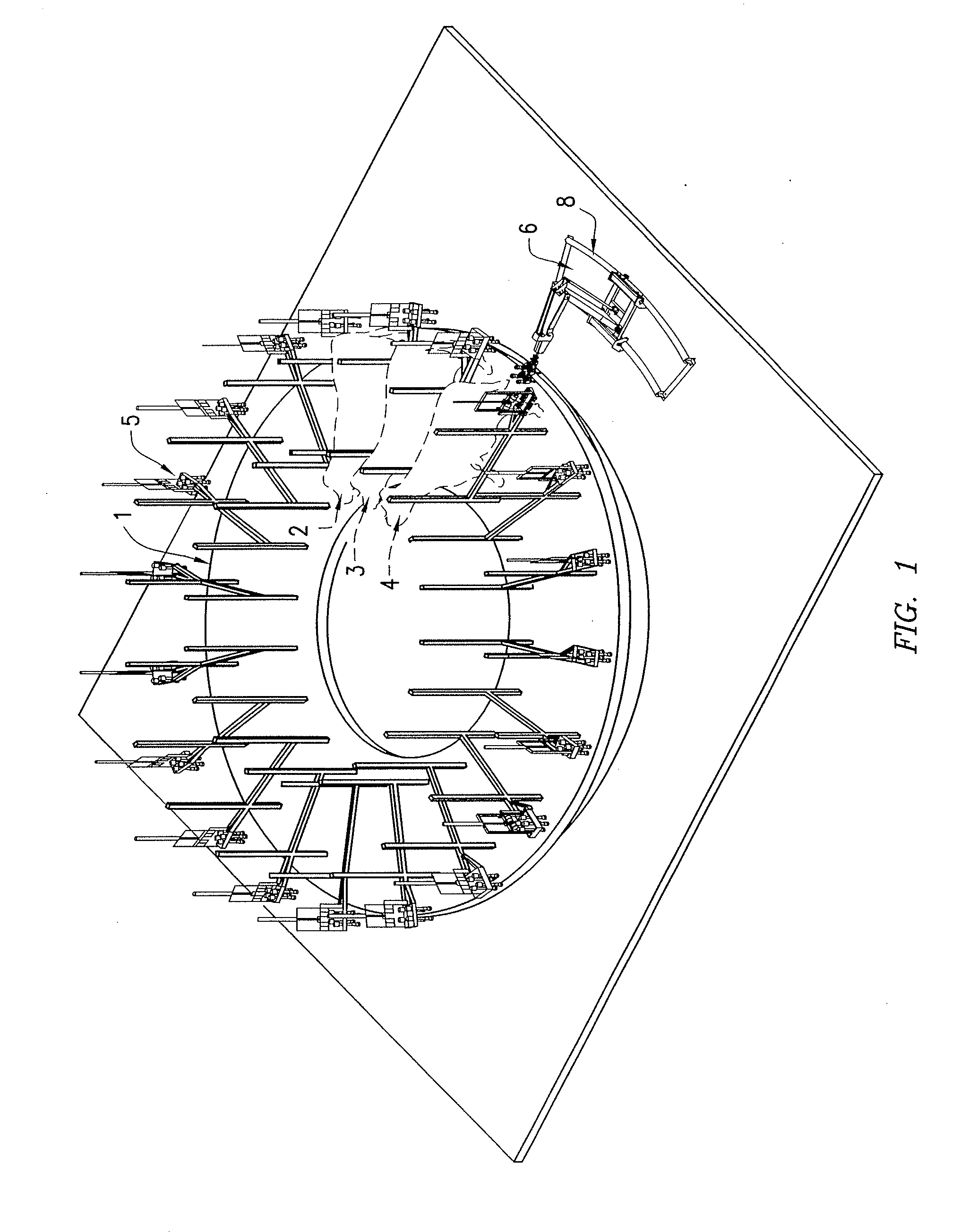
[0029]With reference first to FIG. 1 schematically a cow's rotor 1 is shown carrying some cows 2, 3, 4.

[0030]The rotor 1 can carry a series of cows 2, 3, 4 at multiple circumferentially provided positions, whereby with each position there is also a milking rack 5 at which the milking cups may occupy their first resting position. The robot 6 is arranged to take the milking cups from the milking rack and move them in a second operational position in which the milking cups are connected to the teats of a cow 2, 3, 4 which has to be milked.

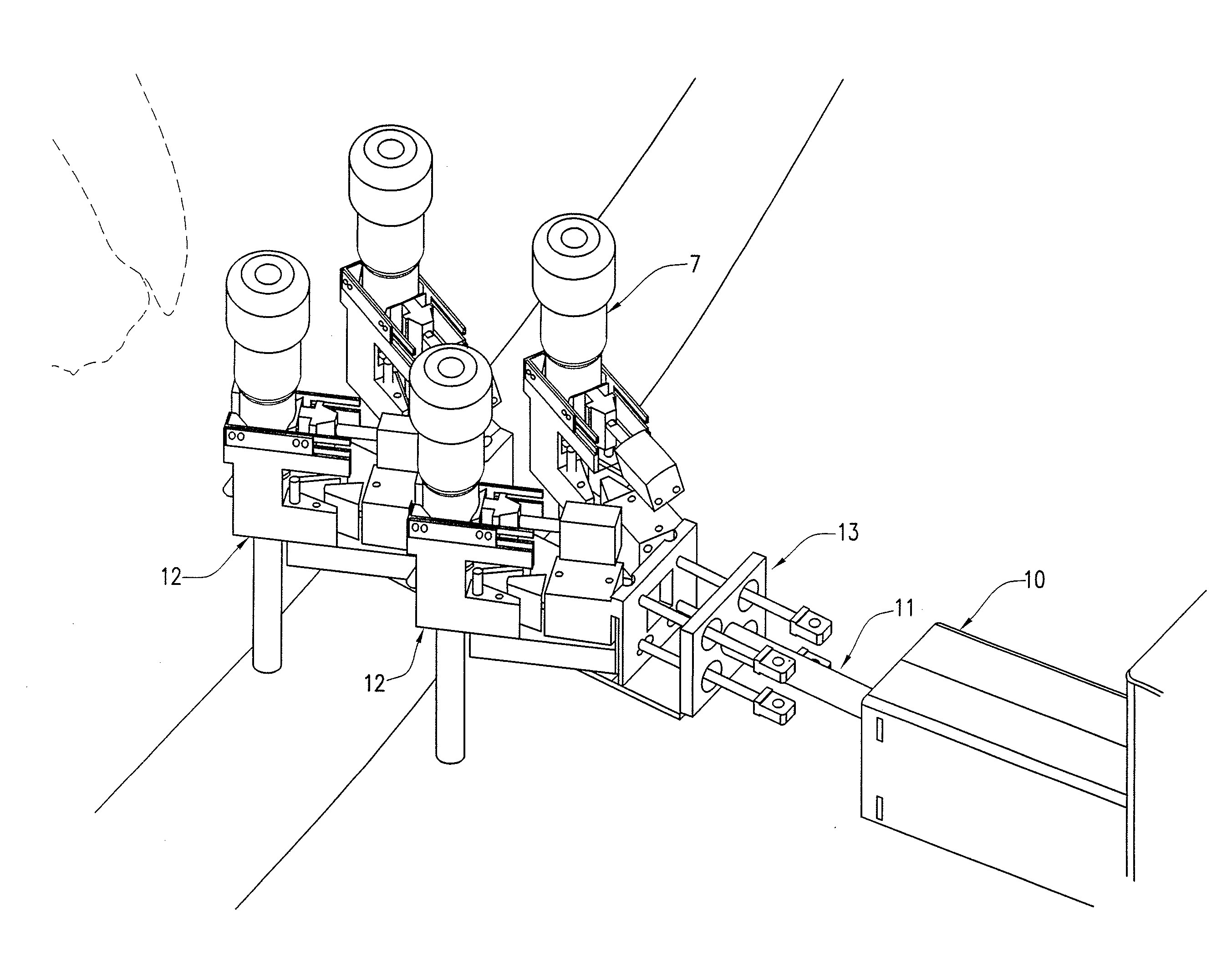
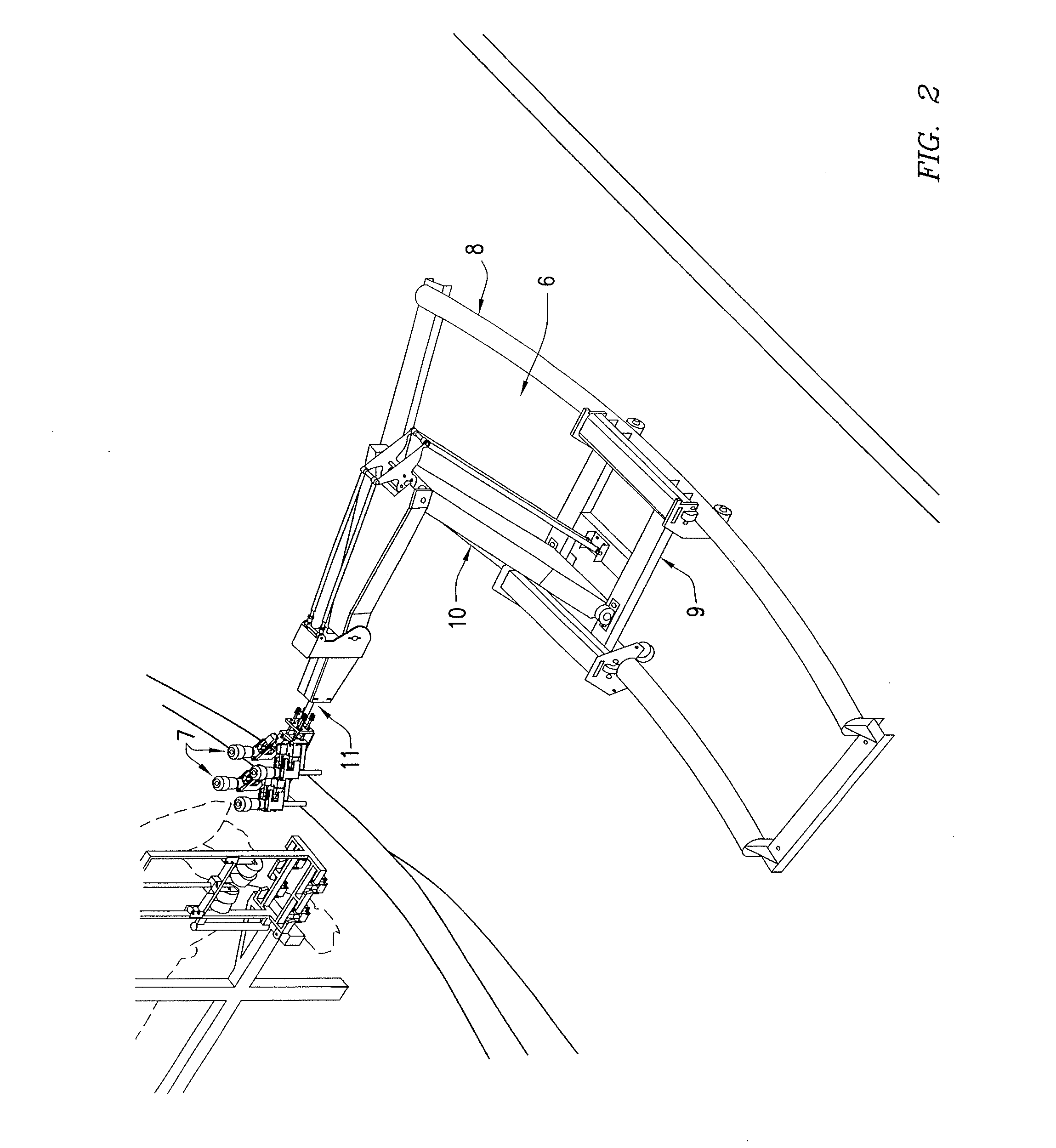
[0031]FIG. 2 shows the robot 6 in more detail in a situation in which it has moved the milking cups 7 already from their first resting position, and prior to having the milking cups 7 placed in the second position.

[0032]FIG. 2 further shows that the robot 6 is movable along a guide track 8 which is at the circumference of the rotatable cow roto...


PUM


Abstract

A milking robot comprises a frame that is movable along a guide track that is positioned adjacent to a rotary platform such that the frame can move in conjunction with the movement of the rotary platform. The milking robot further comprises a moveable arm having a first end that couples to the frame and a second end that extends in a longitudinal direction, and at least one gripper coupled to the movable arm at the second end. The gripper is extendable in the longitudinal direction of the movable arm.

Description

CROSS-REFERENCE TO RELATED APPLICATIONS[0001]This application is a continuation of U.S. patent application Ser. No. 14 / 165,803 filed Jan. 28, 2014 which is a continuation of U.S. patent application Ser. No. 13 / 260,730 filed Nov. 23, 2011 and entitled “ROBOT AND METHOD FOR MILKING A COW BY THIS ROBOT” which is now U.S. Pat. No. 8,640,646 issued Feb. 4, 2014, which claims the benefit of PCT / NL2010 / 050154 filed Mar. 25, 2010 which claims the benefit of NL 2002678 filed Mar. 27, 2009.TECHNICAL FIELD OF THE INVENTION[0002]The invention relates to a robot for moving a milking cup or milking cups from a first resting position to a second operational position or vice versa, in which second position it connects to cow's teat or teats for collecting milk.BACKGROUND OF THE INVENTION[0003]Accordingly the invention also relates to a method for milking a cow, by using a robot for automatically handling milking cups that are near to the cow, wherein the robot handles the milking cups between a fir...

Claims


Application Information

Patent Timeline
Patent Type & Authority Applications(United States)
IPC IPC(8): A01J5/017A01J5/04
CPCA01J5/041A01J5/017A01K1/126A01J5/0175
Inventor VAN DER SLUIS, PETER WILLEMHOFMAN, HENK
Owner TECH HLDG
Learn More