Bone screws and methods of use thereof

a technology of bone screws and washers, applied in the field of devices, can solve the problems of screw loosening, screw loosening, and the possibility of bone screws to back out after implantation

Active Publication Date: 2015-10-01
INNOVISION CO LTD
View PDF7 Cites 44 Cited by
  • Summary
  • Abstract
  • Description
  • Claims
  • Application Information

AI Technical Summary

Benefits of technology

[0049]In other embodiments, the method further includes, prior to step a), joining the washer of the third aspect of the invention to the screw head, whereby tightening or screwing the bone screw into bone of the patient at or near the fracture provides a compression union that stabilizes the fracture.

Problems solved by technology

One drawback associated with prior art bone screws is the potential for the bone screw to back out after implantation.
The use of a solid screw with a bone cement or other fillable material may increase the initial stiffness and strength of the repair, but may not significantly decrease loosening of the screw at the repair site.
The substitution of solid screws with cannulated screws that can extrude a bone cement or other fillable material may improve the strength of the repair while at the same time reducing the likelihood that the screw will loosen and pull out, but distribution of the bone cement or fillable material through the screw and throughout the repair site remains a problem.
In particular, self-hardening bone cements change viscosity after formulation and the even distribution along the length of the bone screw is challenging for such materials.
Another challenge is providing adequate distribution of a bone cement or fillable material while maintaining sufficient screw mechanical strength.
Often increasing the number of delivery channels or ports in the screw body can weaken the bone screw.

Method used


Image

  • Bone screws and methods of use thereof
  • Bone screws and methods of use thereof
  • Bone screws and methods of use thereof

Examples


example 1

Use of a Bone Screw of the Invention to Repair a Fracture or Other Bone Defect

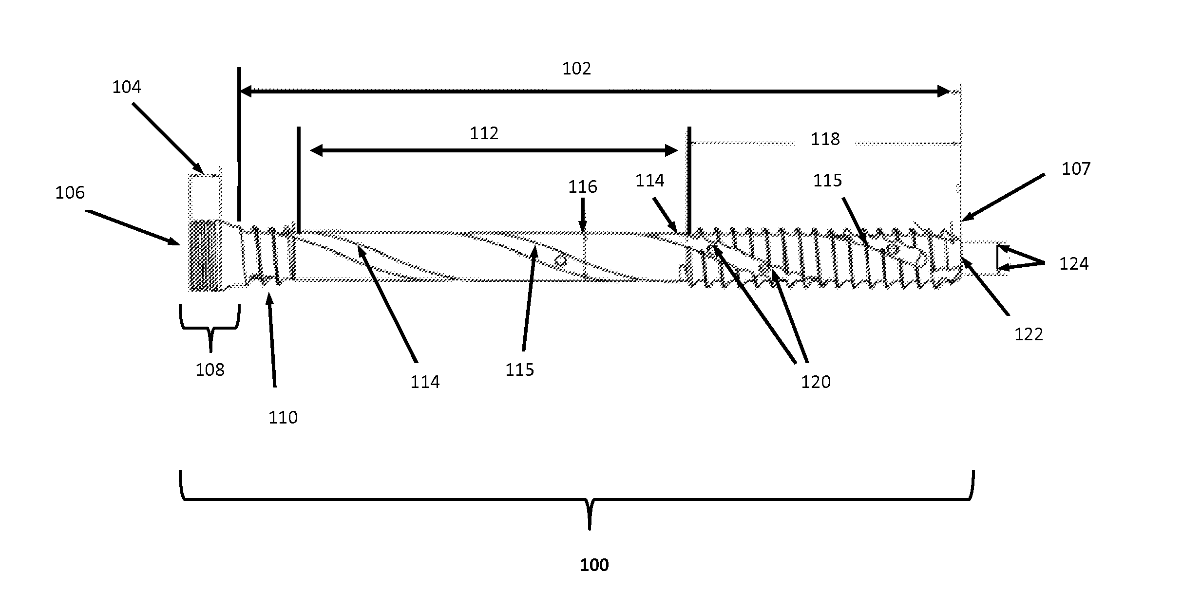
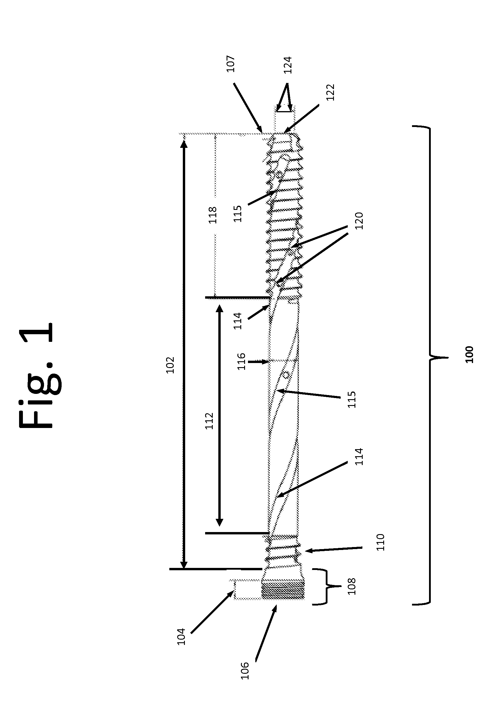
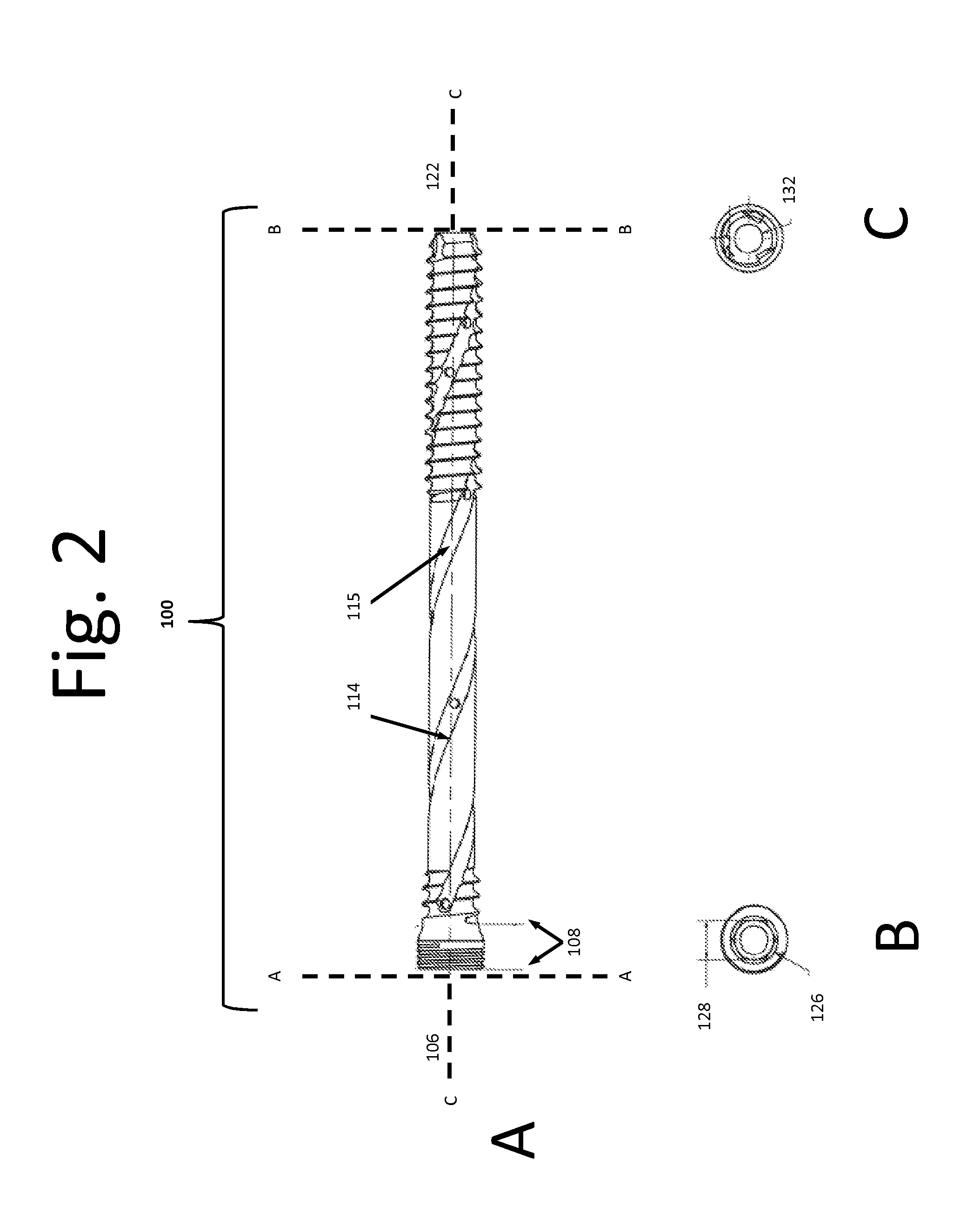
[0162]A bone screw of the invention (e.g., a bone screw of FIGS. 1-5) can be used to provide fracture support, e.g., for a subarticular fracture, in conjunction with conventional fixation. The site to be supported can be accessed using either a percutaneous or open technique. The extraction technique preferably ensures maximal bone conservation.

example 2

Use of a Bone Screw of the Invention for Compression Fixation

[0163]A bone screw of the invention can be used for compression fixation in combination with a washer of the invention to repair a hip fracture. The fractured bone is aligned and held in the proper position by traction.

[0164]A bone screw of the invention is inserted into a washer of the invention. The surgical site is prepared (e.g., by reaming or drilling) to accept the bone screw and body of the washer. The bone screw tip is inserted into the bone such that the threaded portion at the distal end of the body of the bone screw passes beyond the fracture line and into the femoral head. Tightening of the bone screw forces the circumferential lip of the washer against the exterior surface of the bone, which compresses the bone above and below the fracture line, thereby providing compression fixation. A bone cement is injected into the head of the bone screw (e.g., using a manifold of the invention), and hardening of the bone ...

example 3

Use of a Bone Screw of the Invention to Repair a Fracture or Other Bone Defect with Manual Pressure

[0165]A bone model system was used to experimentally determine the forces required to inject a flowable material into a bone screw of the inventive method.

[0166]The clinical objective of bone screws of the invention is to provide secure fixation across a fracture and to enable delivery of a Bone Void Filler (BVF) to the surrounding defect area. It is standard of care to reduce fractures with 4 mm diameter fixation screws. These screws are often used together with BVF material injected around the screw into the fracture site to fill voids.

[0167]We created bone void models (BVM) to simulate a 4.5 milliliter (mL) defect. We used a closed cell 12.5 PCF bone foam to represent typical metaphyseal cancellous bone. Foam blocks were split in half and a hole drilled into each side to form a 4.5 mL hollow cavity when assembled together (FIG. 9).

[0168]The distal end of the bone screw is typically ...


PUM


Abstract

The invention features improved bone screws, a delivery manifold for delivering a flowable medium to a bone screw, and washers for use with the bone screw to provide compressive fixation. The invention also features methods of treatment using the bone screws, washers, and / or delivery manifold, and kits that include the same.

Description

FIELD OF THE INVENTION[0001]The invention relates to devices, in particular, bone screws, washers and bone screw manifolds and methods of use thereof for the treatment of bone defects.BACKGROUND OF THE INVENTION[0002]Fixation tools and devices, which are available in a wide variety of different shapes and sizes, have long been used in the repair of bone defects, such as bone fractures. A physician typically sets the bone to be repaired in the proper position and then uses the fixation tools and devices to secure the bone in that position during the healing process.[0003]A fixation device, such as a bone plate or rod, can be secured to the bone by a fixation tool, such as a bone screw. Alternatively, a bone screw can be used by itself to repair a bone defect. One drawback associated with prior art bone screws is the potential for the bone screw to back out after implantation. To inhibit back out, bone screws have been modified with various thread designs and locking features, with so...

Claims


Application Information

Patent Timeline
Patent Type & Authority Applications(United States)
IPC IPC(8): A61B17/88A61B17/70A61B17/86
CPCA61B17/8811A61B17/863A61B17/7098A61B17/864A61B17/8695A61B17/8841F16B25/0078
Inventor RUSSELL, THOMAS A.
Owner INNOVISION CO LTD
Why Eureka
Try Eureka