Hybrid drive for gas turbine engine

a gas turbine engine and hybrid drive technology, applied in the direction of machines/engines, efficient propulsion technologies, power plant types, etc., can solve the problems of unnecessarily large amount of fuel consumed, difficulty in maintaining electric motors, associated wires, etc., and the power requirements are much lower

Active Publication Date: 2015-10-01
RAYTHEON TECH CORP
View PDF7 Cites 41 Cited by
  • Summary
  • Abstract
  • Description
  • Claims
  • Application Information

AI Technical Summary

Benefits of technology

[0017]In another featured embodiment, a method of operating a gas turbine engine comprises ng the steps of driving a turbine rotor through a clutch to drive an associated fan rotor, and providing an electric motor for selectively driving the fan motor, driving the fan rotor with the clutch closed by the gas turbine engine when an associated aircraft is at a relatively high pow...

Problems solved by technology

However, while the aircraft is in the air at cruise conditions, the power requirements are much lower.
Thus, maintaining the engine operating throughout the entire flight results in a...

Method used


Image

  • Hybrid drive for gas turbine engine
  • Hybrid drive for gas turbine engine
  • Hybrid drive for gas turbine engine

Examples


Embodiment Construction

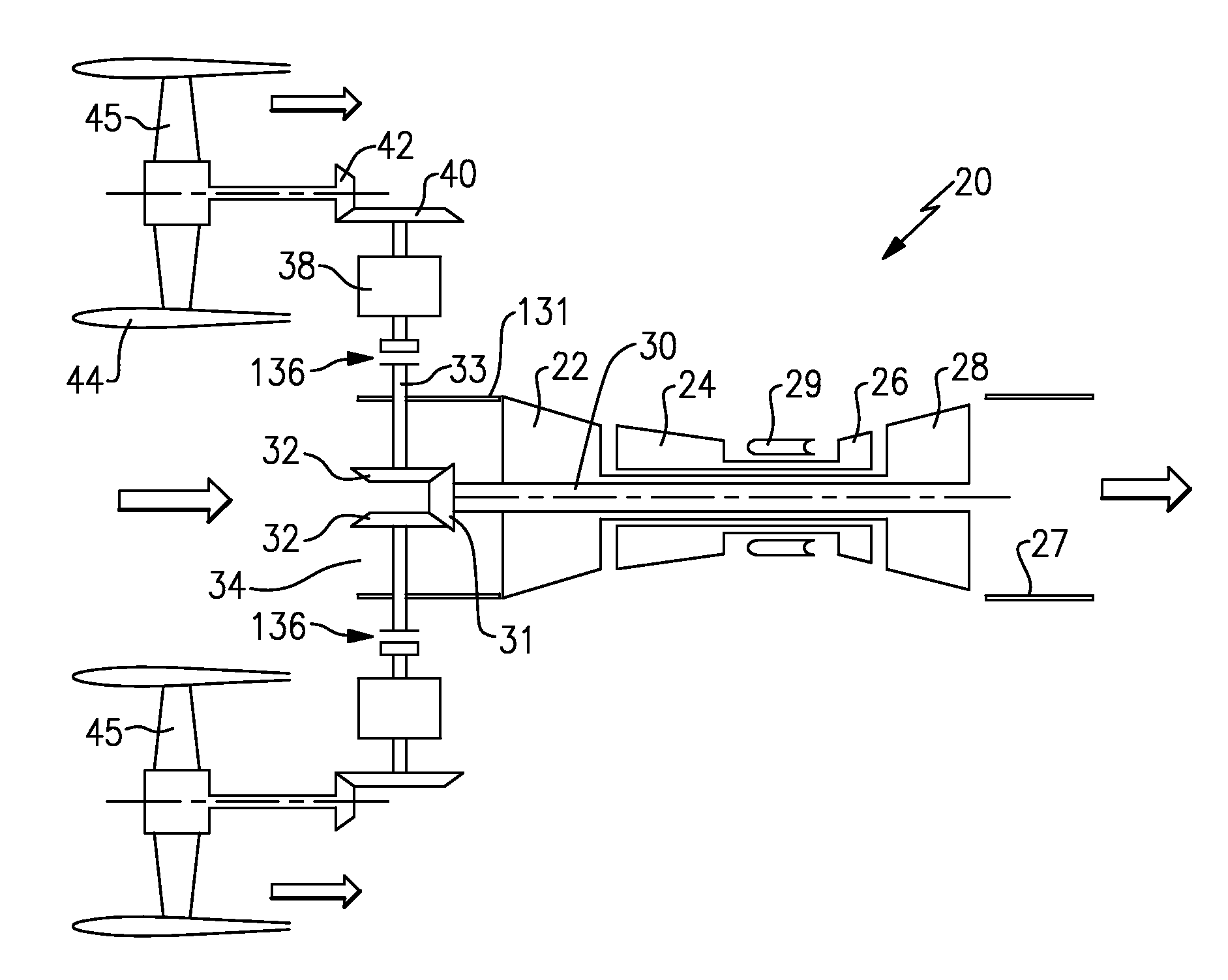
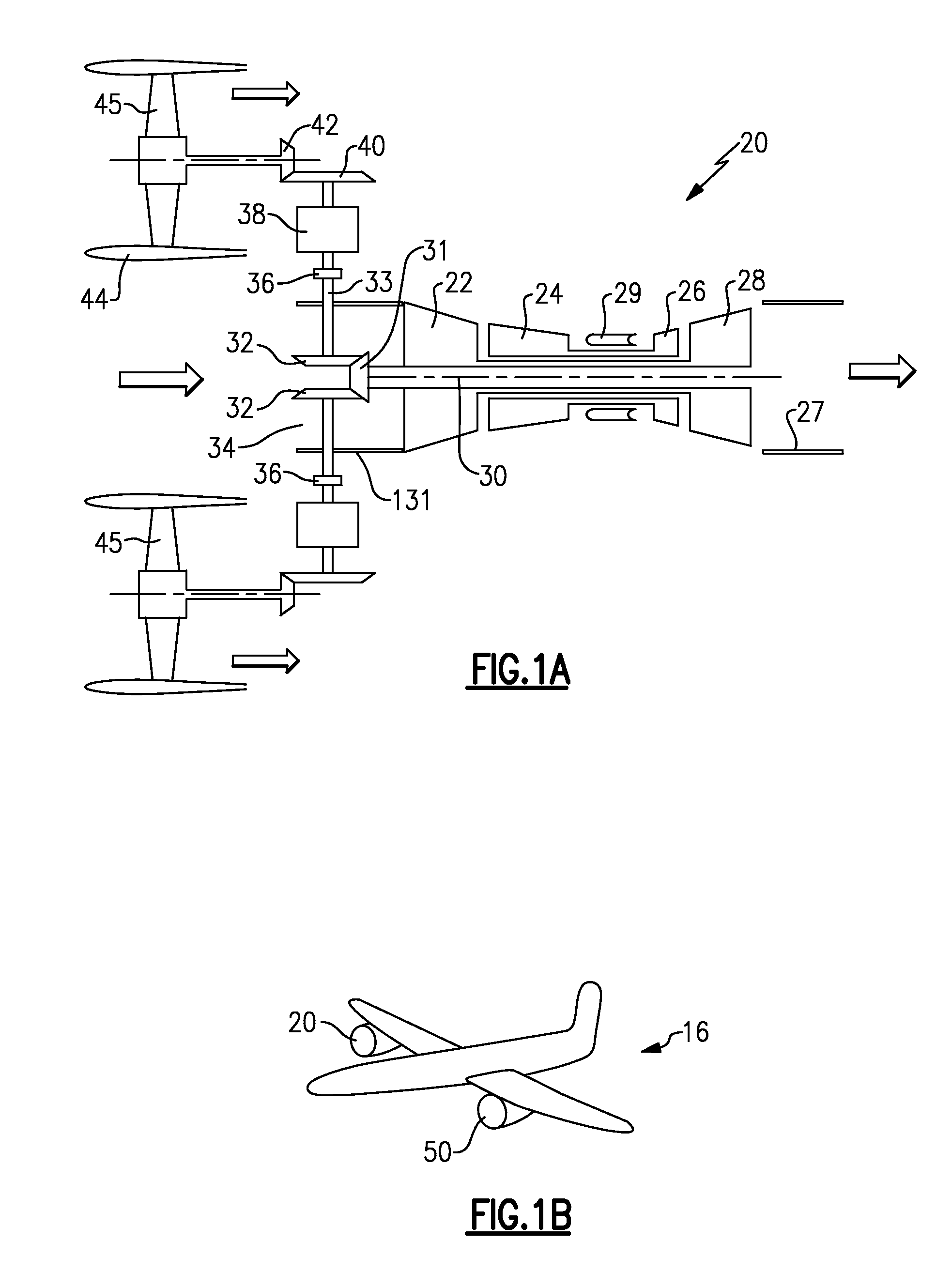
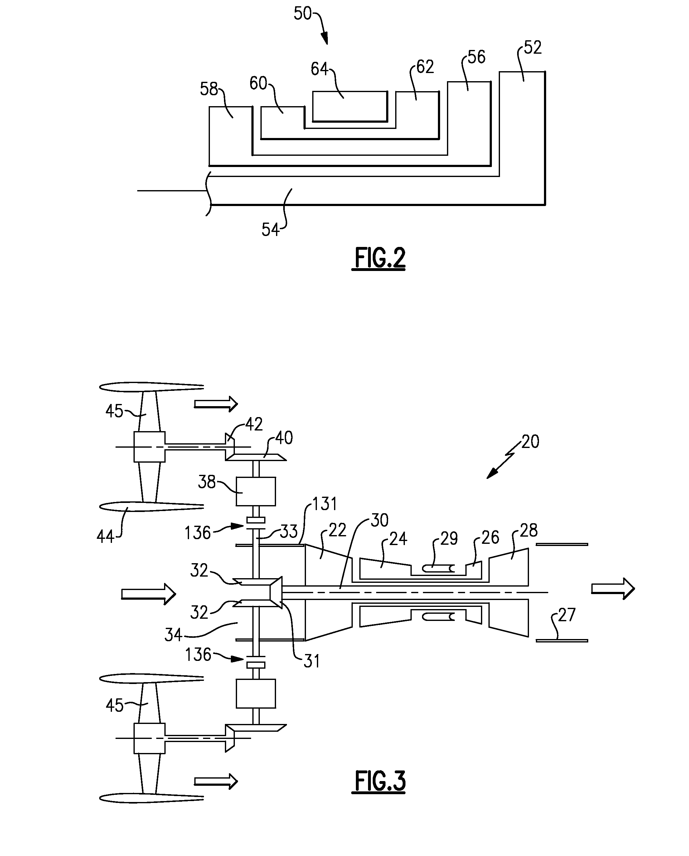
[0032]An engine 20 is illustrated in FIG. 1A having an upstream or low pressure compressor rotor 22, and a downstream or high pressure compressor rotor 24.

[0033]A high pressure or upstream turbine rotor 26 drives compressor rotor 24. A downstream or low pressure turbine rotor 28 drives the compressor rotor 22. A combustion section 29 is positioned intermediate compressor rotor 24 and turbine rotor 26. As known, air is received from a core inlet 34, compressed across compressor rotors 22 and 24. That air is delivered into the combustion section 29 where it is mixed with fuel and ignited.

[0034]Products of this combustion pass downstream over turbine rotors 26 and 28, driving them to rotate. The product of this combustion then passes through an exhaust duct 27. As can be appreciated, products of the combustion in the exhaust duct 27 are very hot.

[0035]A shaft 30 is also driven by the downstream turbine rotor 28, and includes a gear 31 that drives bevel gears 32 to in turn drive a shaft...


PUM


Abstract

A gas turbine engine has a fan drive turbine for selectively driving a fan rotor. A drive shaft between the fan drive turbine and the fan rotor includes a clutch, and an electric motor. The electric motor is positioned such that it is not downstream of a flow path relative to the fan drive turbine. A method of operating a gas turbine engine is also disclosed.

Description

CROSS-REFERENCE TO RELATED APPLICATION[0001]This application claims priority to U.S. Provisional Patent Application No. 61 / 971,086, filed Mar. 27, 2014.BACKGROUND[0002]This application relates to a gas turbine engine, wherein an electric motor may selectively drive a fan rotor at low power conditions of an associated aircraft.[0003]Gas turbine engines are known and are often mounted on aircraft. In a known gas turbine engine, a fan delivers air into a core engine, and into a bypass housing as propulsion air. The air in the core housing passes to a compressor where it is compressed, and then delivered into a combustion section. The air is mixed with fuel in the combustion section and ignited. Products of this combustion pass downstream over a turbine rotor, driving the turbine rotor to rotate, and in turn drive the compressor and fan rotors.[0004]In standard gas turbine engines, the engine is maintained operating throughout the entire flight of the associated aircraft. As known, the ...

Claims


Application Information

Patent Timeline
IPC IPC(8): B64D27/10B64D27/24F02C7/36F02C6/20F02C6/00
CPCB64D27/10F02C6/206F02C6/00F02C7/36Y10S903/903F05D2220/323F05D2270/07B64D2027/026B64D27/24B64D35/02B64D35/04F01D15/12F02K3/077F05D2220/36F05D2240/40F05D2250/312F05D2260/4023F05D2260/4031Y02T50/60
Inventor SHERIDAN, WILLIAM G.
Owner RAYTHEON TECH CORP
Why Eureka
Try Eureka