Hydraulic brake device

a brake device and hydraulic technology, applied in the direction of braking systems, rotary clutches, fluid couplings, etc., can solve the problems of reducing the the risk of not being able to obtain the predetermined braking force, and the remarkably low fluid pressure output of the regulator valve to the auxiliary fluid pressure chamber when the brakes are applied

Inactive Publication Date: 2006-07-20
HONDA MOTOR CO LTD
View PDF8 Cites 22 Cited by
  • Summary
  • Abstract
  • Description
  • Claims
  • Application Information

AI Technical Summary

Benefits of technology

[0033] According to the fifth aspect of the invention, in the event that the output fluid pressure outputted from the fluid pressure output side of the regulator valve decreases down to or lower than the predetermined range which is determined in such a manner as to correspond to operation amounts of the brake operation member due to something abnormal occurring in the regulator valve, since the residual pressure in the accumulator and the residual pressure in the regulator valve can be released through the reservoir which communicates with the fluid line along which the opening/closing valve is provided by way of the same fluid line by changing over the s

Problems solved by technology

Thus, since the residual pressure so acting constitutes a resisting force against the effort applied to the brake pedal and a force which interrupts the forward movement of the valve element, there has existed a risk that a predetermined braking force cannot be obtained.
In addition, in the hydraulic brake device of the JP-A-2002-264795, in the event that there occurs something g

Method used


Image

  • Hydraulic brake device
  • Hydraulic brake device
  • Hydraulic brake device

Examples


Embodiment Construction

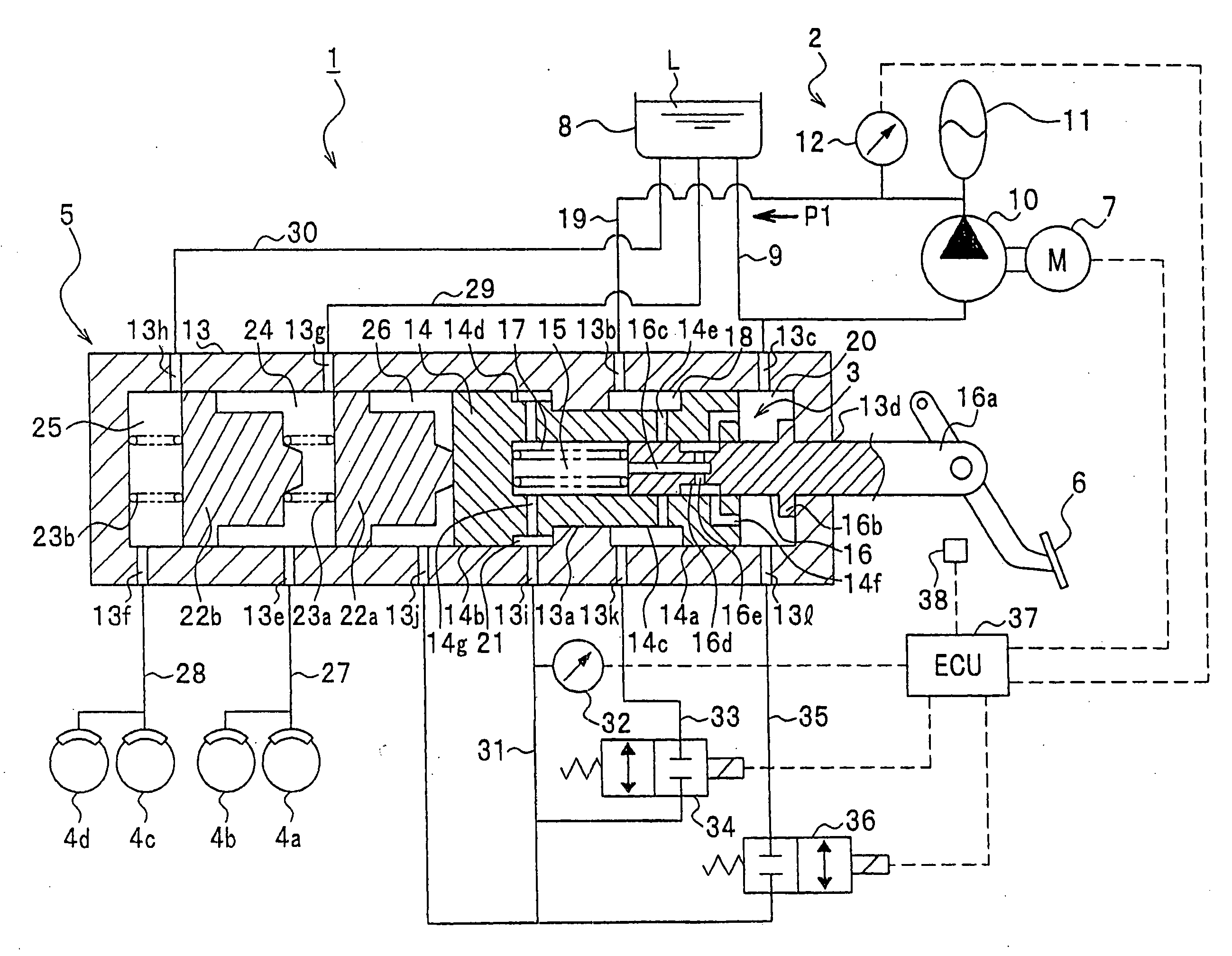
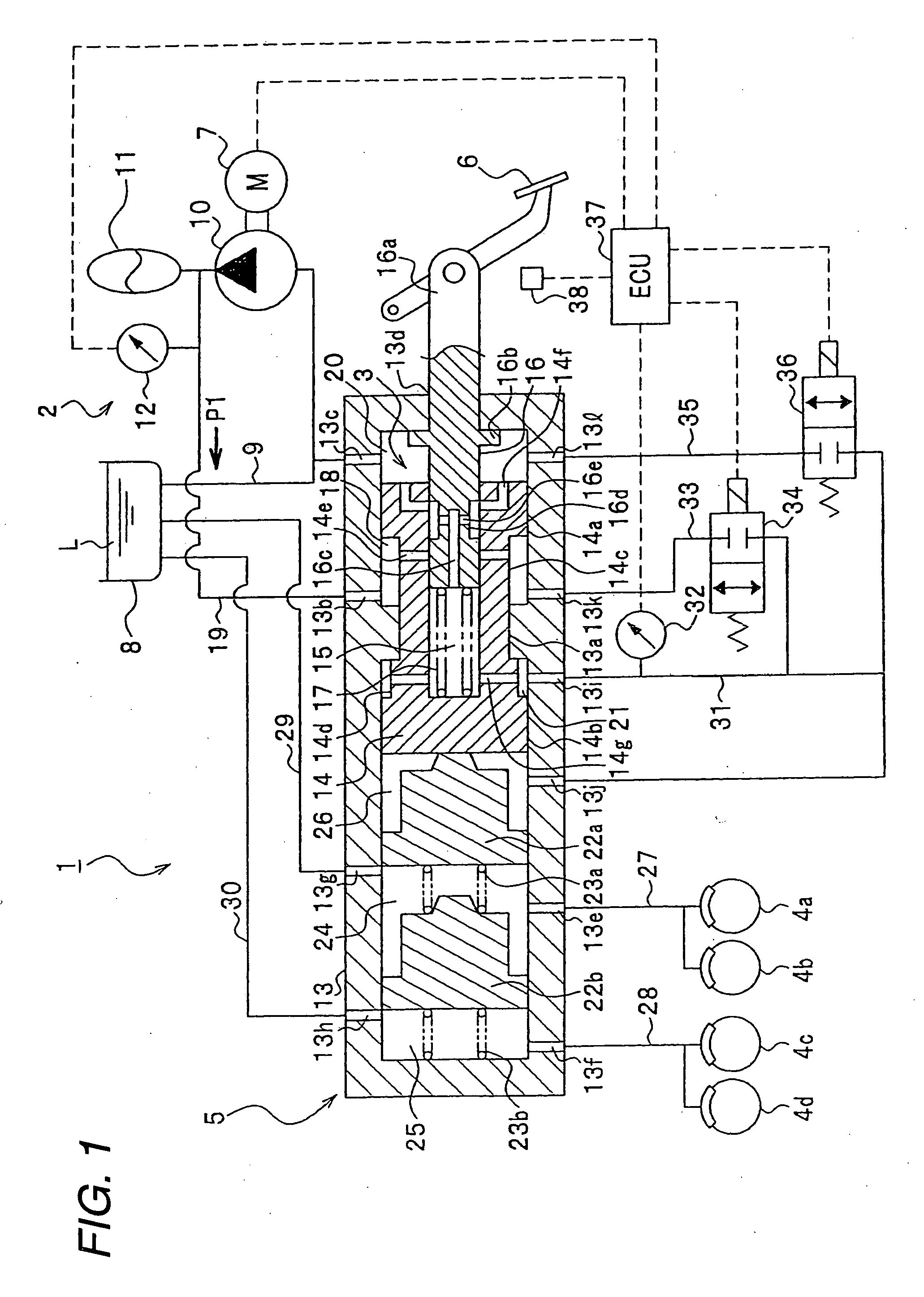
[0038] Hereinafter, the invention will be described based on an embodiment illustrated in the accompanying drawings. FIG. 1 is a schematic diagram which shows the configuration of a hydraulic brake device according to an embodiment of the invention, and in this embodiment, the invention is applied to a hydraulic brake device of a vehicle.

[0039] As shown in FIG. 1, a hydraulic brake device 1 according to the invention includes a fluid pressure generating source 2 which generates a fluid pressure P, a regulator valve 3 which regulates a fluid pressure outputted from the fluid pressure generating source 2, a master cylinder 5 which generates a fluid pressure (a master cylinder pressure) which applies a braking force to wheel cylinders 4a, 4b, 4c, 4d of respective wheel brakes by virtue of a fluid pressure (an output fluid pressure) that is outputted from the regulator valve 3, and a brake pedal 6.

[0040] The fluid pressure generating source 2 includes a motor 7, a pump 10 which is dri...


PUM


Abstract

A normally closed secondary solenoid opening/closing valve 36 is provided along a secondary branched fluid pipe 35 establishing a communication between an accumulator 11 and a reservoir 8 through a fluid pressure input side to a fluid pressure output side of a regulator valve 3, and in the event that a fluid pressure supplied to the regulator valve 3 decreases down to or lower than a predetermined range due to something abnormal occurring in the accumulator 11, the state of the secondary solenoid opening/closing valve 36 is changed over from a closed state to an opened state, whereby a residual pressure in the accumulator 11 and a residual pressure in the output fluid pressure chamber 15 can be released through the reservoir 8 which is in communication therewith through an output fluid pipe 31 and the secondary branched fluid pipe 35 along which the secondary opening/closing valve 36 is provided.

Description

[0001] The present invention claims foreign priority to Japanese patent application No. P.2005-009067, filed on Jan. 17, 2005, the contents of which is incorporated herein by reference. BACKGROUND OF THE INVENTION [0002] 1. Field of the Invention [0003] The present invention relates to a hydraulic brake device. [0004] 2. Description of the Background Art [0005] As a hydraulic brake device provided on a vehicle such as an automobile, there exists a hydraulic brake device which is disclosed in, for example, Japanese Patent Unexamined Publication No. JP-A-2002-264795 (claim 1, FIG. 1). This hydraulic brake device includes a fluid pressure source having an accumulator which accumulates therein operating fluid, a regulator valve which regulates a fluid pressure supplied from the fluid pressure source in accordance with an effort applied to a brake pedal for output, a master cylinder which is activated by virtue of a fluid pressure supplied from the regulator valve to an auxiliary fluid p...

Claims


Application Information

Patent Timeline
IPC IPC(8): B60T8/44
CPCB60T13/145B60T13/147
Inventor AOKI, YASUSHIKANAGAWA, AKIHARU
Owner HONDA MOTOR CO LTD
Why Eureka
Try Eureka