
System for monitoring a period of an operation clock signal of a CPU and stopping operations of the CPU when the period is out of a predetermined allowable range

a technology of a clock signal and a monitoring circuit, which is applied in the direction of unauthorized memory use protection, instruments, generating/distributing signals, etc., can solve the problems of easy disassembly and removal of the monitoring function of the countermeasure for hacking, and achieve the effect of easy disassembly and removal of the clock monitoring circui

Inactive Publication Date: 2006-07-18
RENESAS ELECTRONICS CORP +1
View PDF7 Cites 20 Cited by
  • Summary
  • Abstract
  • Description
  • Claims
  • Application Information

AI Technical Summary

Benefits of technology

[0005]However, in regard to the countermeasure technique for hackers, it has been proved that function of a clock monitoring circuit can be disabled easily when a hacker applies, for example, a voltage higher than the predetermined value to an input node of the clock monitoring circuit. Moreover, in the case of forming a clock monitoring circuit to monitor the clock frequency, the system for detecting a period by generating a voltage depending on pulse width of clock with a time-constant circuit consisting of a capacitance element and a resistance element can be realized more easily from the viewpoint of circuit configuration but this system also includes a demerit that the capacitance element forming the time-constant circuit becomes comparatively large in size and therefore it may be found easily by a hacker.
[0007]However, such countermeasure for hacker also has a demerit that the monitoring function can be easily disabled, for example, when a hacker removes the protection shield by applying a voltage higher than the predetermined voltage value to an input node of the voltage detecting circuit connected to the protection shield.
[0008]It is an object of the present invention to provide a technique to prevent discontinuation of monitoring circuit by a hacker in the microcomputer for IC card including a clock monitoring circuit as a countermeasure for hacker.
[0009]It is another object of the present invention to provide a microcomputer for IC card which assures high level protection of secret information of chip from illegal attack by a hacker.
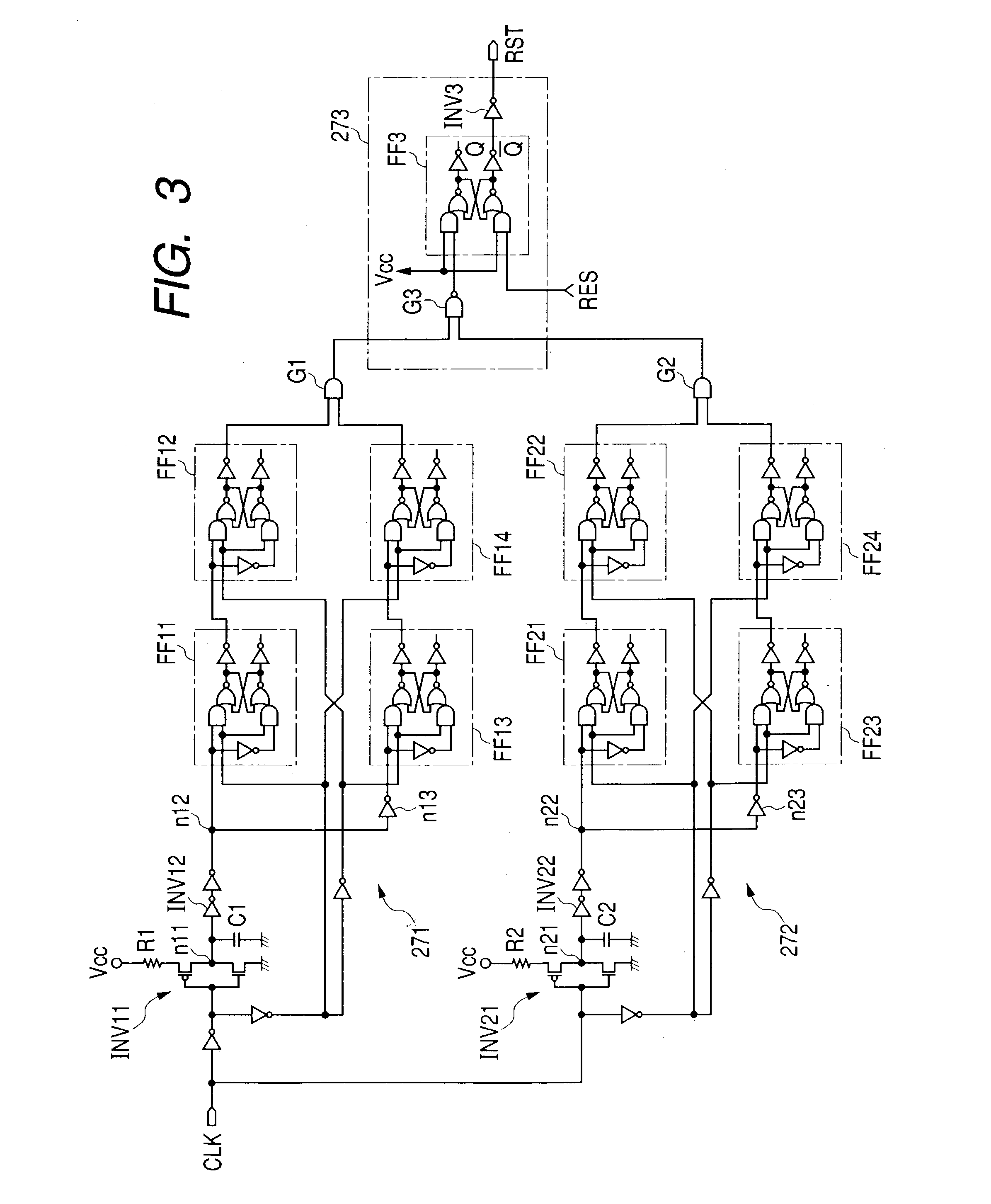
[0012]According to an aspect of the present invention, a pulse width detecting circuit for generating a voltage depending on the pulse width of clock signal and a clock monitoring circuit including a discriminating circuit for discriminating the voltage generated by the pulse width detecting circuit with the predetermined threshold value level in the microcomputer for IC card including the clock monitoring circuit are given the function to judge an output of the discriminating circuit when the clock rises and falls, namely two times in one cycle. Accordingly, even when a hacker applies a signal of the predetermined frequency or higher to an input node of the clock monitoring circuit or when a hacker fixes a voltage of the input node, the clock monitoring circuit detects this event and operation of microcomputer for IC card can be stopped by generating, for example, a reset signal. Therefore, illegal action to discontinue the function of clock monitoring circuit can be prevented.
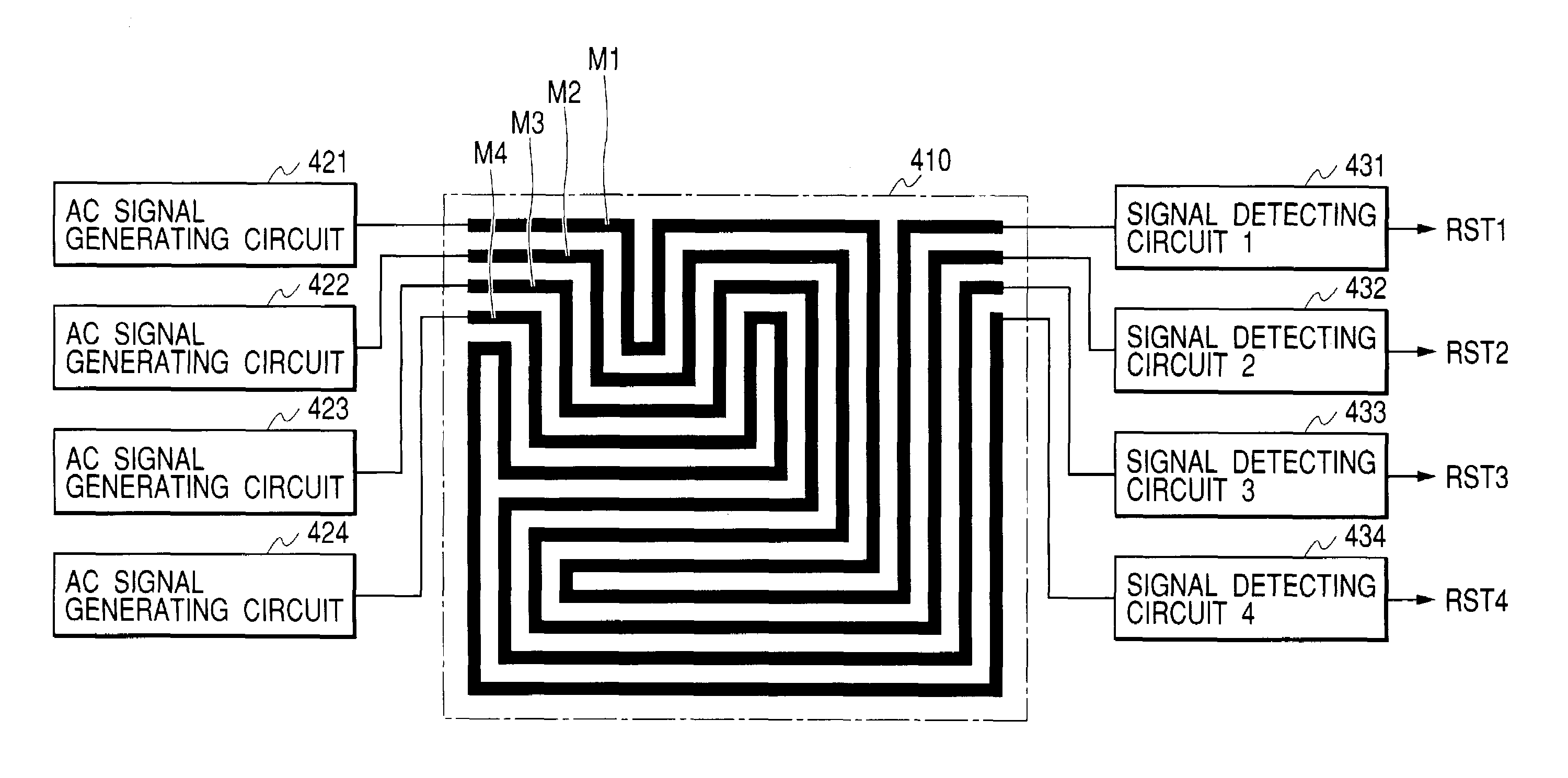
[0013]According to another aspect of the present invention, a protection shield is formed of a plurality of shielded wires and AC signals of different frequencies are impressed to one terminal of each shielded wire, while a disconnection detecting circuit consisting of a frequency detecting circuit is connected to the other terminal of the shielded wire. Thereby, when a hacker disconnects the protection shield, a disconnection detecting circuit detects this event to stop operation of chip by generating a reset signal. Accordingly, the illegal action to discontinue the function of protection shield can be prevented. For enlargement of area of shielded area with a small number of signals, it is recommended to provide the meandering shielded wire. More preferable result can also be obtained by providing such shielded wire in a pattern like a labyrinth drawn without lifting a pen from the paper surface.

Problems solved by technology

However, in regard to the countermeasure technique for hackers, it has been proved that function of a clock monitoring circuit can be disabled easily when a hacker applies, for example, a voltage higher than the predetermined value to an input node of the clock monitoring circuit.
However, such countermeasure for hacker also has a demerit that the monitoring function can be easily disabled, for example, when a hacker removes the protection shield by applying a voltage higher than the predetermined voltage value to an input node of the voltage detecting circuit connected to the protection shield.

Method used


Image

  • System for monitoring a period of an operation clock signal of a CPU and stopping operations of the CPU when the period is out of a predetermined allowable range
  • System for monitoring a period of an operation clock signal of a CPU and stopping operations of the CPU when the period is out of a predetermined allowable range
  • System for monitoring a period of an operation clock signal of a CPU and stopping operations of the CPU when the period is out of a predetermined allowable range

Examples


embodiment 1

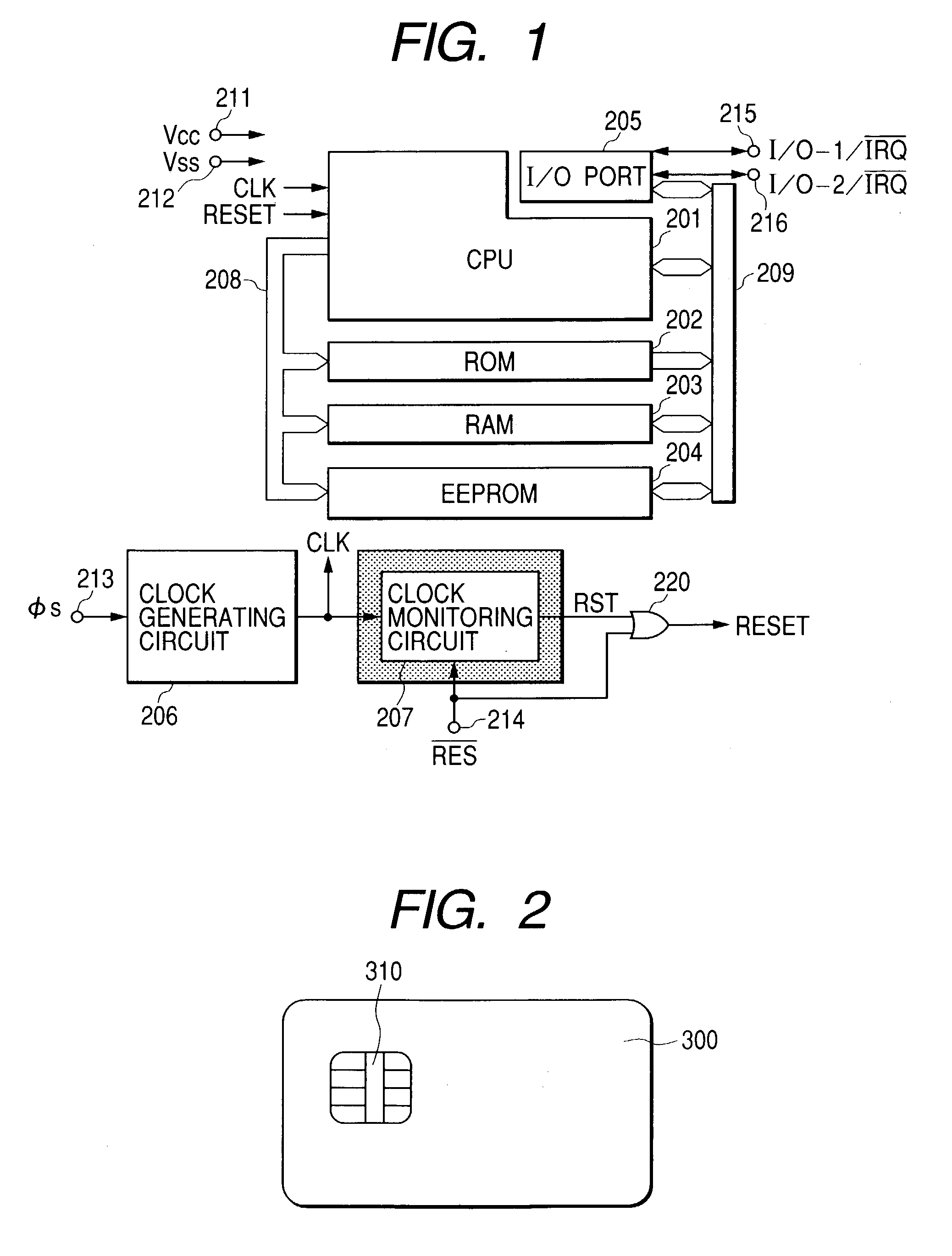
[0024]FIG. 1 illustrates an example of configuration of a microcomputer for IC card to which the present invention can be applied effectively. In FIG. 1, 201 designates a CPU (Central Processing Unit) of the program control system for totally controlling a chip; 202, a ROM (Real Only Memory) for storing programs to be executed by the CPU and fixed data required for execution of programs; 203, a RAM (Random Access Memory) for providing a working area and a temporary storing area of the CPU201; 204, an EEPROM (Electrically Erasable and Programmable Read Only Memory) as a non-volatile memory for electrically erasing and writing data; 205, an external interface as an input / output port for transmitting and receiving signals between the system within the chip and an external device of card; 206, a clock generating circuit for generating a system clock φs required for operation of CPU201 and EEPROM204 by waveform shaping and frequency division of the clock signal CLK supplied from an exter...

embodiment 2

[0053]FIG. 7 and FIG. 8 illustrate an embodiment of a security means in the present invention. The security means in this embodiment is configured with a metal shield region 410 consisting of a plurality of signal lines MSL1, MSL2, . . . formed at the upper part of the substrate surface where a circuit is provided on the chip to be protected from illegal attach by a hacker, AC signal generating circuits 421, 422, . . . connected to one terminals (starting terminals) of the signal lines MSL1, MSL2, . . . for shielding to transfer AC signals of different frequencies or amplitudes to respective signal lines, and signal detecting circuits 431, 432, . . . consisting of detecting circuits for detecting frequencies or amplitudes of AC signals transferred from respective signal lines.

[0054]The signal detecting circuits 431, 432, . . . detect input signals and generate reset signals RST1, RST2, . . . when the input signals do not have predetermined frequencies or amplitudes and then supply a...


PUM


Abstract

There is provided a technology for preventing disabling of function of a clock monitoring circuit by a hacker in a microcomputer for IC card provided with a clock monitoring circuit as a countermeasure for a hacker. In the microcomputer for IC card provided with the clock monitoring circuit, the clock monitoring circuit is given the function to perform the detecting operation twice during one cycle, namely at the timings of rise and fall of the clock.

Description

BACKGROUND OF THE INVENTION[0001]The present invention relates to a semiconductor integrated circuit such as a microcomputer and microprocessor and more specifically to a technique which may be effectively applied to protect secret information of chip from illegal attack by hackers, for example, the technique which may be effectively applied to a microcomputer and microprocessor as a data processing device to be built into an IC card.[0002]In recent years, instead of magnetic card as an information storage medium, attention is paid to a microprocessor as a data processing device comprising a built-in central processing unit (CPU) and an IC card comprising a built-in semiconductor integrated circuit (IC) such as microprocessor. An IC card is thought as a medium which can be effectively applied into a cash-card or a credit-card because of its higher security in comparison with a magnetic card. However, such IC card is used to process the data having higher secrecy of information becau...

Claims


Application Information

Patent Timeline
Patent Type & Authority Patents(United States)
IPC IPC(8): G08B21/00G06F1/04B42D15/10G06F1/24G06F12/14G06F21/60G06F21/75G06K19/07G06K19/073
CPCG06F21/55G06F21/77G06F21/558G06F21/755
Inventor MORIYAMA, NAOKATSUSHINOHARA, SHIGERU
Owner RENESAS ELECTRONICS CORP
Learn More