Lens array and image display device incorporating the same

Active Publication Date: 2015-10-01
RICOH KK
View PDF1 Cites 22 Cited by
  • Summary
  • Abstract
  • Description
  • Claims
  • Application Information

AI Technical Summary

Benefits of technology

[0013]An object of the present invention is to provide an image display device which can effectively reduce visible interfering no

Problems solved by technology

However, due to the coherence of a laser beam, interfering noise such as speckle is likely to occur in an observed image.
Interference fringes bring about degradation of image quality and visibility.
However, to emit the light beam in pulse in synchronization with scanning and illuminate only the micro lenses,

Method used


Image

  • Lens array and image display device incorporating the same
  • Lens array and image display device incorporating the same
  • Lens array and image display device incorporating the same

Examples


Embodiment Construction

[0023]Hereinafter, an embodiment of an image display device will be described in detail with reference to the accompanying drawings. Wherever possible, the same reference numbers will be used throughout the drawings to refer to the same or like parts.

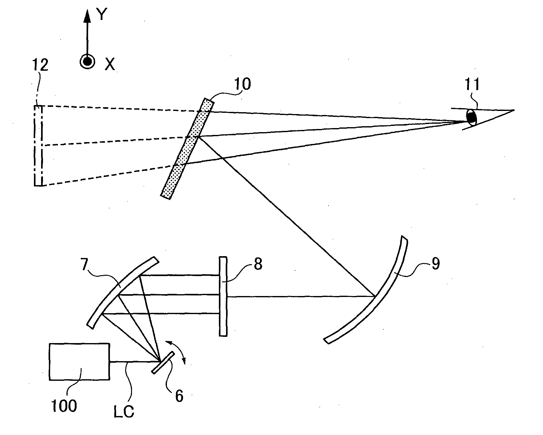
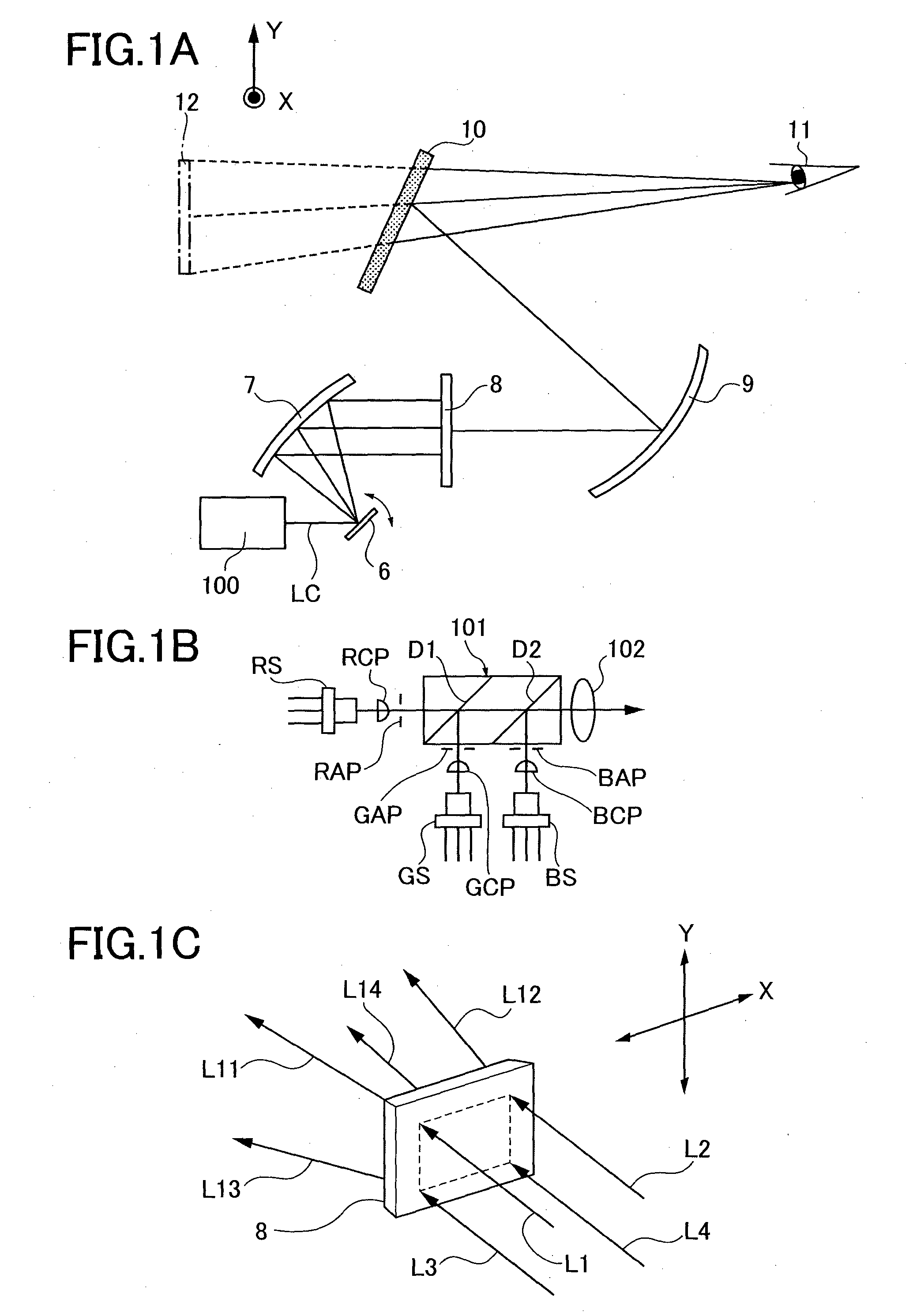
[0024]FIGS. 1A to 1C show one example of an image display device according to the present embodiment.

[0025]The image display device is a headup display device to display two-dimensional color images. FIG. 1A shows the overall structure of the device.

[0026]In FIG. 1A the image display device comprises a light source 100, an optical deflector 6, concave mirrors 7, 9, a micro lens array 8, and a reflective element 10.

[0027]The light source 100 projects a light beam LC for color image display. The light beam LC is a light beam formed by combining red (R), green (G), and blue (B) color beams into one.

[0028]The structure of the light source 100 is shown in FIG. 1B by way of example. The light source 100 includes semiconductor lasers RS, GS, B...


PUM


Abstract

An image display device includes a light source, an imaging element to form an image with a light beam from the light source, and a lens array illuminated with the light beam forming the image for image display, in which lenses are arranged closely to each other. In which in the lens array a curvature radius of a surface of a border of neighboring lenses is set to be smaller than a wavelength of the light beam.

Description

CROSS REFERENCE TO RELATED APPLICATION[0001]The present application is based on and claims priority from Japanese Patent Application No. 2012-279736, filed on Dec. 21, 2012 and No. 2013-221274, filed on Oct. 24, 2013.TECHNICAL FIELD[0002]The present invention relates to a lens array and an image display device incorporating the lens array.BACKGROUND ART[0003]The image display device can be incorporated as a headup display device in various kinds of an operable vehicle such as automobile, train, ship and vessel, helicopter, airplane.[0004]Japanese Patent Application Publication No. 2009-128659 (Reference 1) and No. 2010-145745 (Reference 2) disclose a headup display device as an image display device which two-dimensionally scans alight beam to display an image.[0005]This device includes a deflector to two-dimensionally deflect a light beam modulated in intensity by an image signal and scans a micro lens array with the deflected light beam to form an image thereon. The image is enlarg...

Claims


Application Information

Patent Timeline
IPC IPC(8): G02B27/01G02B3/00
CPCG02B3/0056G02B27/0101G02B26/101G02B27/48G02B17/0605
Inventor INAMOTO, MAKOTOSAISHO, KENICHIROHSATOH, YASUHIROWATANABE, JUN
Owner RICOH KK
Why Eureka
Try Eureka