
Method of exposure control and image pickup apparatus

an exposure control and image technology, applied in the field of exposure control and image pickup devices, can solve the problems of excessive exposure, manual operation of the zoom lens, and the inability of the ae control to follow the zooming speed, so as to suppress the manufacturing cost of the image pickup apparatus and the amount of change in the focal luminance

Inactive Publication Date: 2009-01-15
ELMO CO LTD
View PDF3 Cites 18 Cited by
  • Summary
  • Abstract
  • Description
  • Claims
  • Application Information

AI Technical Summary

Benefits of technology

[0012]Therefore, an object of the present invention is to provide an exposure control method which can maintain the brightness of output image at a constant value even when the focal luminance is suddenly changed by high-speed zooming or by changes in the luminance of an external object such as lightning detection, and an image pickup apparatus realizing the exposure control method.
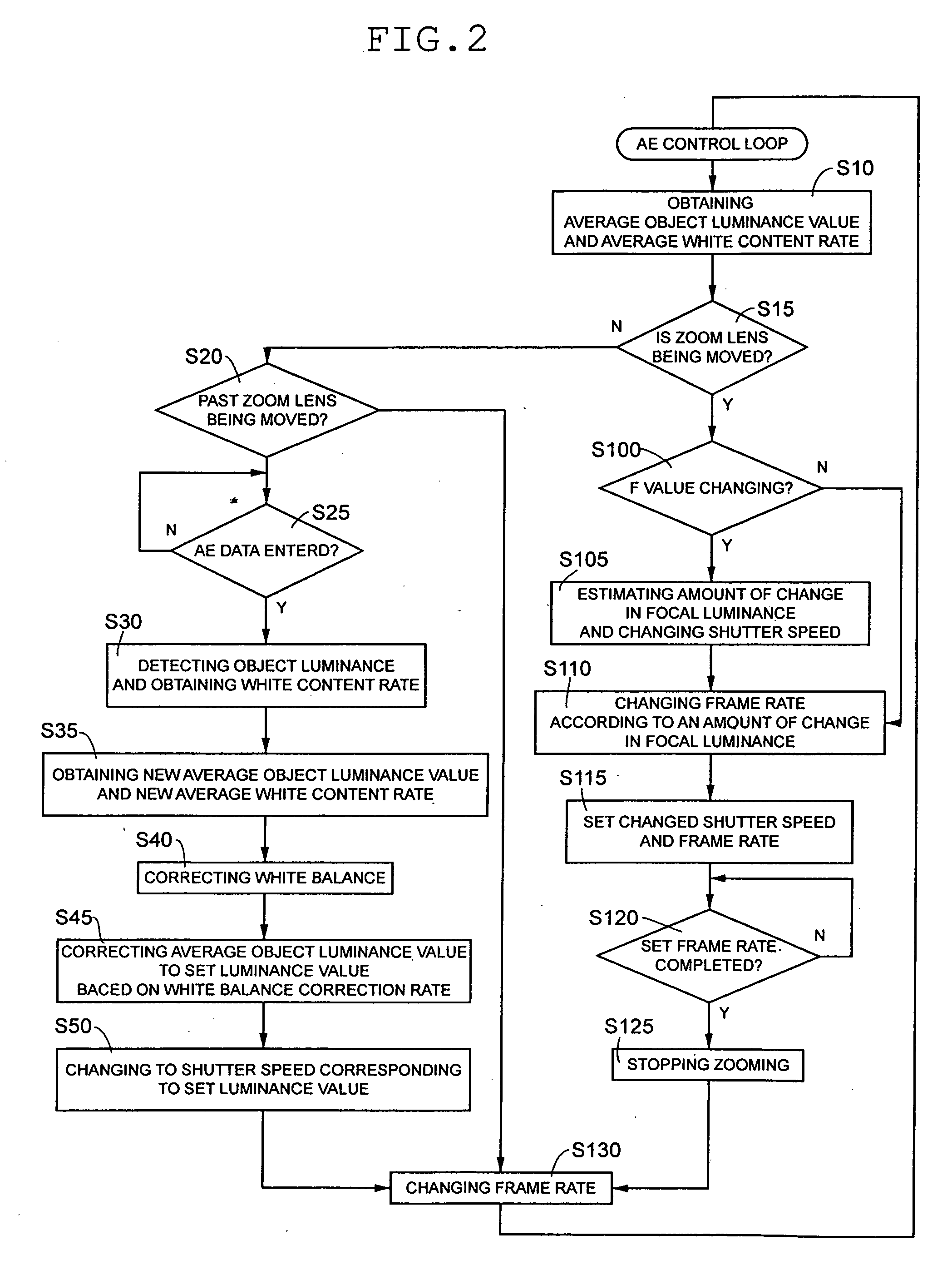
[0014]According to the above-described method, when the focus lens is moved with delay relative to the movement of the zoom lens, whether the zooming speed is high or not is determined depending upon whether the F value is changed or not. When the F value has been changed, the focus lens lags behind the zoom lens, namely, it is determined that the focus luminance has changed and the brightness of output image has changed. Then, the shutter speed in the normal processing of the AE control is forced into a change. Consequently, the change in the brightness in the output image can be suppressed.
[0016]According to the above-described method, it is determined that the AF control is appropriate in the case where the zoom lens is determined to be in motion even when the F value does not change. In this case, the shutter speed is controlled so as to match the zooming speed. Consequently, the brightness of the output image can be maintained at a constant value.
[0020]The object luminance values monitored for a predetermined period of time are averaged, so that an averaged object luminance value is obtained. An initial change ratio refers to a change ratio of the average object luminance value and the object luminance value at the time of initial detection of the change. On the basis of a shutter speed changed according to the initial change ratio, a change ratio obtained from a subsequently sequentially detected object luminance and the average object luminance value are compared with each other. When the ratios do not correspond to each other, the shutter speed changed by the change ratio is corrected into a reference shutter speed. Consequently, since the shutter speed is corrected so as to be changed constantly at a change ratio obtained from an initially detected amount of change, a change in the focal luminance can be rendered substantially constant. Consequently, a change in the brightness of an image can be prevented from sudden change.
[0022]According to the above-described configuration, an amount of change in the focal luminance can be estimated using known AE control unit and AF control unit. Consequently, since the conventional AE control unit and AF control unit can be used, the manufacturing costs of the image pickup apparatus can be suppressed.

Problems solved by technology

However, the following two problems arise when the zoom lens is manually operated at high speeds.
In the first problem, when the zoom lens is moved from a wide-angle end to a telephoto end, the AE control cannot follow the zooming speed, whereupon exposure becomes excessive such that an output image becomes white or flies white.
Furthermore, in the second problem, when the zoom lens is moved from the telephoto end to the wide-angle end, the AE control cannot follow the zooming speed alike, whereupon exposure becomes insufficient such that an output image becomes dark.
In this case, there is a possibility that the brightness may change as described above although the change is transient, whereupon the changes in the focal luminance cannot sufficiently be suppressed.

Method used


Image

  • Method of exposure control and image pickup apparatus
  • Method of exposure control and image pickup apparatus
  • Method of exposure control and image pickup apparatus

Examples


Embodiment Construction

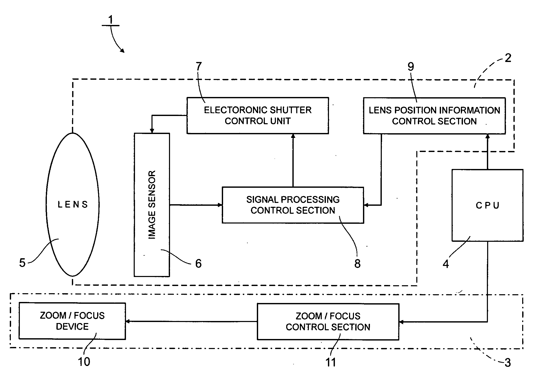
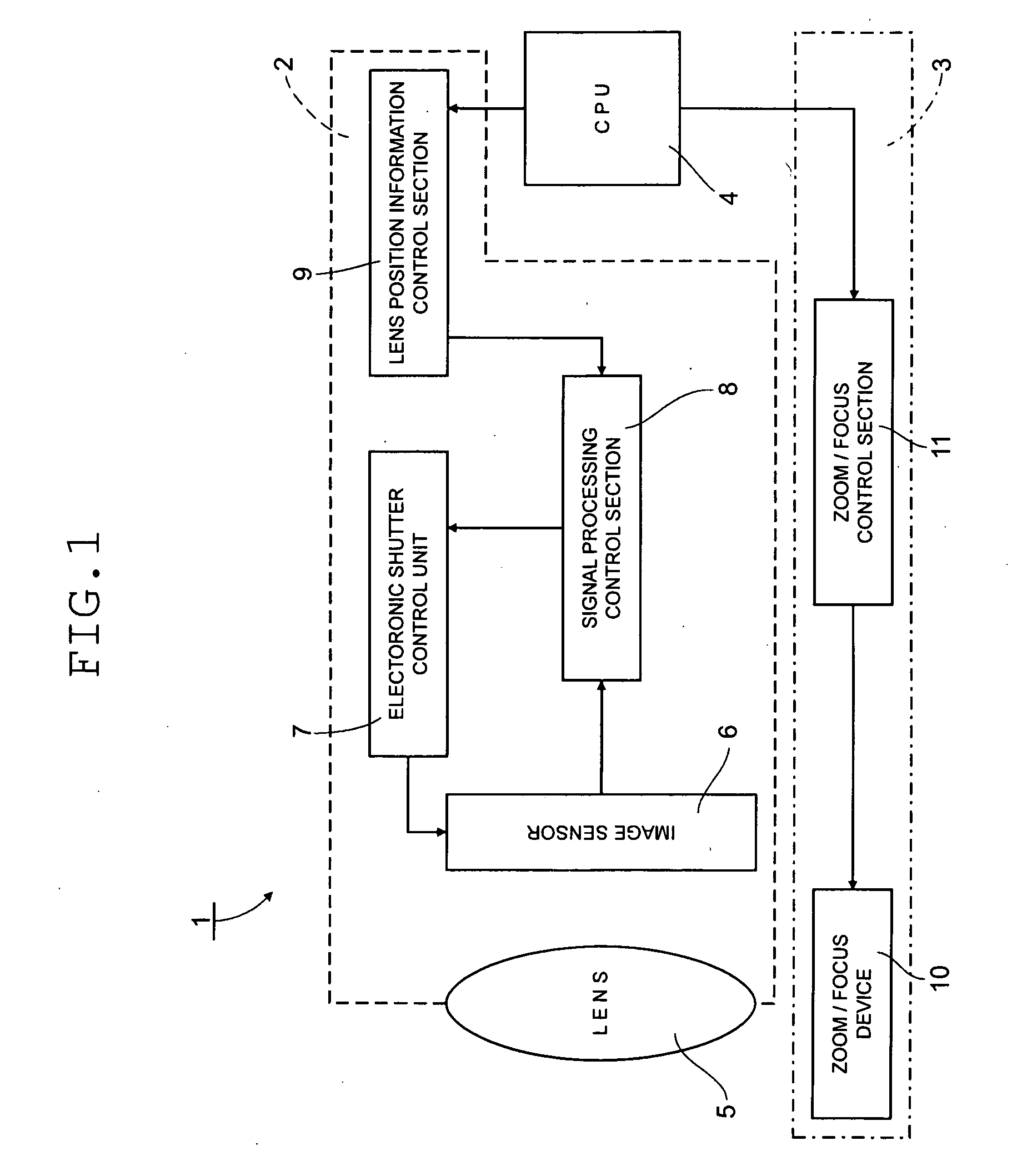
[0031]An embodiment will be described with reference to the accompanying drawings. Referring to FIG. 1, an arrangement of an image pickup apparatus 1 of the embodiment is shown. The image pickup apparatus 1 comprises an image pickup section 2, an autofocus (AF) control section 3 and a central processing unit (CPU) 4. The image pickup section 2 comprises a lens group 5, an image sensor 6, an electronic shutter control section 7, a signal processing control section 8 and a lens position control section 9.

[0032]The lens group 5 comprises a plurality of lenses such as a zoom lens and a focus lens but is shown as a single lens for the sake of simplicity in FIG. 1. The image sensor 6 is made by arranging a solid-state image sensing device comprising a charge coupled device (CCD) into a lattice shape. The solid-state image sensing device is located on an imaging plane in the rear of the lens group 5. The electronic shutter control section 7 oscillates pulses for every predetermined period ...


PUM


Abstract

A method of exposure control in an image pickup apparatus includes determining whether a zoom lens has been moved, determining whether an F value obtained from information about focal position of a focus lens linked to movement of the zoom lens has changed, estimating a variation in the focus luminance before and after a change in the F value from the F values before and after the change when the F value has been changed, changing the shutter speed determined according to a focus luminance before the change to a shutter speed determined according to the focus luminance after the change, based on the estimated variation in the focus luminance, and changing a frame rate determined according to the focus luminance before the change to a frame rate determined according to a focus luminance after the change according to the changed shutter speed.

Description

CROSS-REFERENCE TO RELATED APPLICATIONS[0001]This application is based upon and claims the benefit of priority from the prior Japanese Patent Application No. 2007-105750, filed on Apr. 13, 2007, the entire contents of which are incorporated herein by reference.BACKGROUND OF THE INVENTION[0002]1. Field of the Invention[0003]The present invention relates to a method of exposure control and an image pickup device realizing the exposure control method.[0004]2. Description of the Related Art[0005]Image pickup apparatus such as digital cameras comprise a solid-state image sensor such as a charge coupled device (CCD) or a complementary metal oxide semiconductor (CMOS). The solid-state image sensor is provided in a lattice-like arrangement on an imaging plane. The image sensor is exposed to light and electrical charge by light reception is sequentially transferred to be read out by a signal control section or the like so that an image is taken. Subsequently, an analog signal is converted in...

Claims


Application Information

Patent Timeline
Patent Type & Authority Applications(United States)
IPC IPC(8): H04N5/232G03B7/093H04N5/235H04N101/00
CPCG03B7/093H04N5/2351H04N5/23296H04N5/23212H04N23/67H04N23/69H04N23/71G03B7/20H04N23/73
Inventor HIBINO, YUTAKANAKAYAMA, YOSHIHIKOFURUYA, MASATAKA
Owner ELMO CO LTD
Learn More