Cylinder head structure for internal combustion engine and internal combustion engine

a technology of internal combustion engine and cylinder head, which is applied in the direction of machines/engines, valve drives, mechanical equipment, etc., can solve the problems of thermal deformation inside the cam carrier, the relative displacement between the cylinder head and the cam carrier occurs, and the surface damage of the fretting, so as to reduce the relative position and relative angle between the camshaft and the cam bearing, inhibit the wear or seize of the cam bearing

Active Publication Date: 2020-06-23
ISUZU MOTORS LTD
View PDF19 Cites 0 Cited by
  • Summary
  • Abstract
  • Description
  • Claims
  • Application Information

AI Technical Summary

Benefits of technology

[0020]According to the cylinder head structure for the internal combustion engine and the internal combustion engine of the present disclosure, even if the internal combustion engine, in which the monolithic cam carrier is placed on the top of the cylinder head, is under a running condition of the engine, under which a difference in temperature between the cylinder head and the cam carrier occurs, a relative displacement between the cylinder head and the cam carrier can be absorbed, thereby inhibiting contact sites between the cylinder head and the cam carrier from being damaged due to fretting. In addition, by absorbing a thermal deformation caused by unevenness in temperature inside the cam carrier, amounts of change in relative position and relative angle between the camshaft and the cam bearings can be reduced. Therefore, it is possible to maintain a coaxial machining accuracy of the cam bearings fitted on the respective transversal frames of the cam carrier, thereby inhibiting wear or seizing of the cam bearings.

Problems solved by technology

However, if an internal combustion engine, in which the monolithic cam carrier is fixed on the top of a cylinder head, is under a running condition of the engine, under which a difference in temperature between the cam carrier and the cylinder head occurs, such as a running condition in which the engine is suddenly transmitted from a low load running such as a cold state to a high load running, or a running condition in which the engine is suddenly transmitted from the high load running to the low load running or a no-load running (a state where an engine brake is activated), there are problems that a relative displacement between the cylinder head and the cam carrier occurs due to a difference in temperature therebetween or that a thermal deformation occurs due to a difference in thermal expansion between a contact surface of the cam carrier with the cylinder head and an upper surface side of the cam carrier opposite thereto.
As a result, fretting which is a surface damage caused when minute reciprocating sliding repeatedly acts thereon occurs.
An upper surface side of the cam carrier which is opposite to the cylinder head is difficult to follow the temperature of the cylinder head since a heat transfer thereto is slower and an amount of heat radiated therefrom is large.
Therefore, a difference temperature occurs between the contact surface side and the upper surface side and a difference between an amount of thermal expansion of the contact surface side and an amount of thermal expansion of the upper surface side occurs, thereby causing a thermal deformation inside the cam carrier.
If the thermal deformation is caused, a position or inclined angle of the cam bearings relative to the camshaft is changed, thereby causing problems, such as wear or seizing of the cam bearings.
However, in this cylinder head, since the cast iron bearing member is casted in the aluminum cam carrier, there arises a problem that due to a difference in thermal expansion between aluminum alloy and cast iron, a thermal stress caused by a difference in amount of thermal deformation always acts outside a specific temperature range.
In addition, since the amount of thermal expansion of the cam carrier is suppressed to be small, there arises a problem that a relative displacement between the cylinder head main body and the cam carrier placed thereon is increased.

Method used


Image

  • Cylinder head structure for internal combustion engine and internal combustion engine
  • Cylinder head structure for internal combustion engine and internal combustion engine
  • Cylinder head structure for internal combustion engine and internal combustion engine

Examples


first embodiment

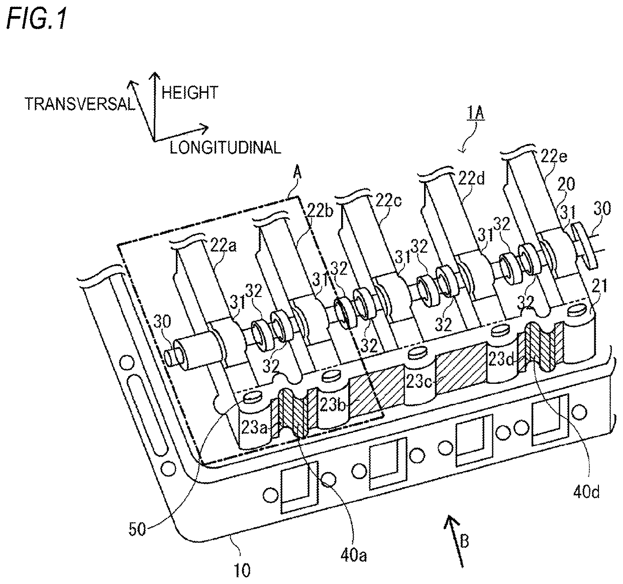
[0029]A cylinder head structure 1A for an internal combustion engine according to the present disclosure is a structure in which a monolithic cam carrier 20 is placed on the top of a cylinder head 10 and then is fixed thereto by bolts 50 as shown in FIG. 1.

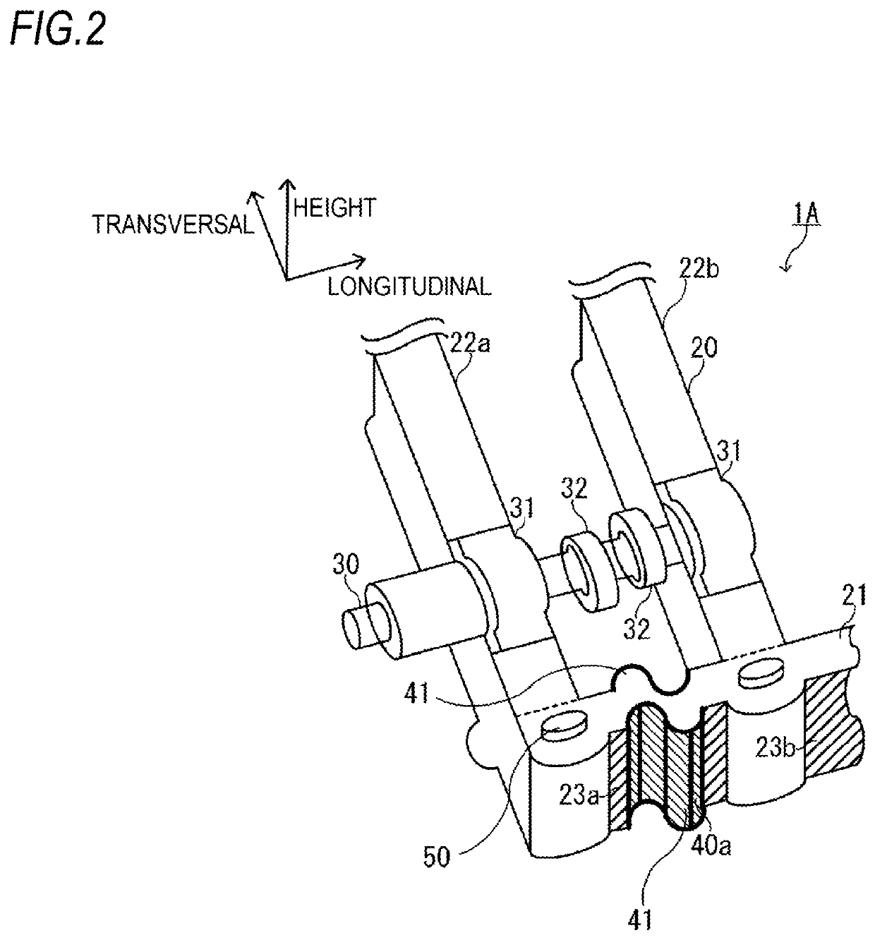
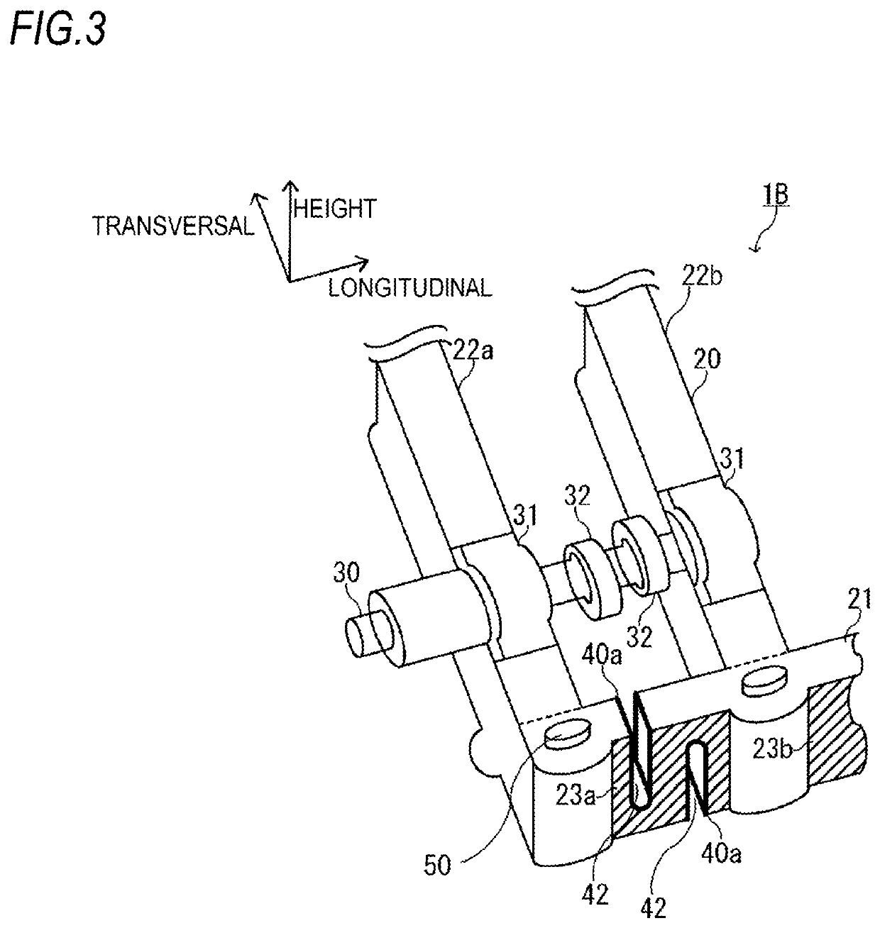
[0030]Also, in the cylinder head structure 1 for the internal combustion engine, the cam carrier 20 includes a pair of longitudinal frames 21 provided parallel to an axial direction (longitudinal direction) of a camshaft 30 and a plurality of transversal frames 22 (22a, 22b, 22c, 22d, 22e) connected to the pair of longitudinal frames 21 to be spaced from each other and supporting the camshaft 30 via cam bearings 31.

[0031]Herein, directions as shown in FIG. 1 will be described. A longitudinal direction is a longitudinal direction of the cylinder head 20 and is the same as an axial direction of the camshaft 30. Also, this direction is the same as an axial direction of the cam bearings 31 arranged on the respective transversal frames...


PUM


Abstract

A cam carrier includes a pair of longitudinal frames provided parallel to an axial direction of a camshaft and a plurality of transversal frames connected to the pair of longitudinal frames to be spaced from each other and supporting the camshaft via cam bearings. A flexible structure suppressing amounts of change in a relative position and an inclined angle of the cam bearings relative to the camshaft due to a thermal expansion is provided on at least one of wall surfaces of the longitudinal frames, the wall surfaces being located between adjacent transversal frames.

Description

CROSS-REFERENCE TO RELATED APPLICATIONS[0001]This application is a U.S. National Stage entry of PCT Application No: PCT / JP2016 / 082563 filed Nov. 2, 2016, which claims priority to Japanese Patent Application No. 2015-219400, filed Nov. 9, 2015, the contents of which are incorporated herein by reference.TECHNICAL FIELD[0002]The present disclosure relates to a cylinder head structure for an internal combustion engine and an internal combustion engine, in which a monolithic cam carrier is placed on a top of a cylinder head.BACKGROUND ART[0003]In general, most of internal combustion engines, such as diesel engines, are configured as a multi-cylinder engine provided with a plurality of cylinders. In a case where an OHC (overhead cam carrier) is employed for a valve mechanism in the multi-cylinder engine, multi-cylinder engine includes a camshaft having a plurality of cams for opening and closing an intake valve and an exhaust valve arranged on an upper portion of the inside of each cylind...

Claims


Application Information

Patent Timeline
Patent Type & Authority Patents(United States)
IPC IPC(8): F01L1/053F02F1/24F01L1/04F01L1/047
CPCF02F1/24F01L1/053F01L1/04F02F2001/244F01L2001/0476F01L2001/0535F01L2810/04
Inventor HIRUKAWA, KOUJI
Owner ISUZU MOTORS LTD
Why Eureka
Try Eureka