Cylinder head structure for internal combustion engine and internal combustion engine

Active Publication Date: 2018-11-08
ISUZU MOTORS LTD
View PDF2 Cites 3 Cited by
  • Summary
  • Abstract
  • Description
  • Claims
  • Application Information

AI Technical Summary

Benefits of technology

The present invention is about a cylinder head structure for an internal combustion engine and an internal combustion engine that can prevent damage to the engine caused by friction between parts. This is achieved by absorbing the relative displacement between the cylinder head and the cam carrier, which can occur when the engine is under running condition. Additionally, the invention can reduce the thermal deformation caused by uneven temperature inside the cam carrier, which can affect the accuracy of the cam bearings and cause wear and seizing.

Problems solved by technology

However, if an internal combustion engine, in which the monolithic cam carrier is fixed on the top of a cylinder head, is under a running condition of the engine, under which a difference in temperature between the cam carrier and the cylinder head occurs, such as a running condition in which the engine is suddenly transmitted from a low load running such as a cold state to a high load running, or a running condition in which the engine is suddenly transmitted from the high load running to the low load running or a no-load running (a state where an engine brake is activated), there are problems that a relative displacement between the cylinder head and the cam carrier occurs due to a difference in temperature therebetween or that a thermal deformation occurs due to a difference in thermal expansion between a contact surface of the cam carrier with the cylinder head and an upper surface side of the cam carrier opposite thereto.
As a result, fretting which is a surface damage caused when minute reciprocating sliding repeatedly acts thereon occurs.
An upper surface side of the cam carrier which is opposite to the cylinder head is difficult to follow the temperature of the cylinder head since a heat transfer thereto is slower and an amount of heat radiated therefrom is large.
Therefore, a difference temperature occurs between the contact surface side and the upper surface side and a difference between an amount of thermal expansion of the contact surface side and an amount of thermal expansion of the upper surface side occurs, thereby causing a thermal deformation inside the cam carrier.
If the thermal deformation is caused, a position or inclined angle of the cam bearings relative to the camshaft is changed, thereby causing problems, such as wear or seizing of the cam bearings.
However, in this cylinder head, since the cast iron bearing member is casted in the aluminum cam carrier, there arises a problem that due to a difference in thermal expansion between aluminum alloy and cast iron, a thermal stress caused by a difference in amount of thermal deformation always acts outside a specific temperature range.
In addition, since the amount of thermal expansion of the cam carrier is suppressed to be small, there arises a problem that a relative displacement between the cylinder head main body and the cam carrier placed thereon is increased.

Method used


Image

  • Cylinder head structure for internal combustion engine and internal combustion engine
  • Cylinder head structure for internal combustion engine and internal combustion engine
  • Cylinder head structure for internal combustion engine and internal combustion engine

Examples


first embodiment

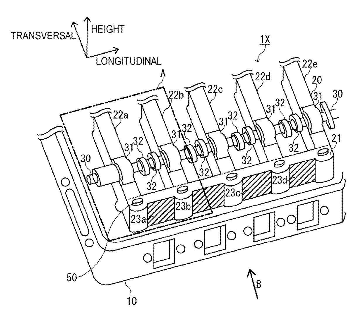
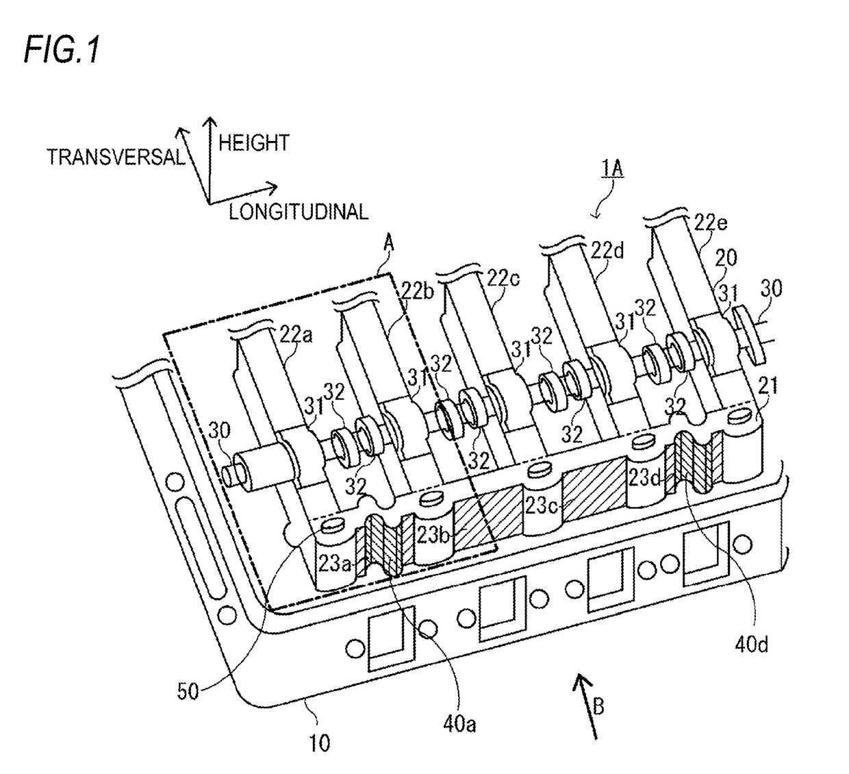
[0028]A cylinder head structure 1A for an internal combustion engine according to the present disclosure is a structure in which a monolithic cam carrier 20 is placed on the top of a cylinder head 10 and then is fixed thereto by bolts 50 as shown in FIG. 1.

[0029]Also, in the cylinder head structure 1 for the internal combustion engine, the cam carrier 20 includes a pair of longitudinal frames 21 provided parallel to an axial direction (longitudinal direction) of a camshaft 30 and a plurality of transversal frames 22 (22a, 22b, 22c, 22d, 22e) connected to the pair of longitudinal frames 21 to be spaced from each other and supporting the camshaft 30 via cam bearings 31.

[0030]Herein, directions as shown in FIG. 1 will be described. A longitudinal direction is a longitudinal direction of the cylinder head 20 and is the same as an axial direction of the camshaft 30. Also, this direction is the same as an axial direction of the cam bearings 31 arranged on the respective transversal frames...

second embodiment

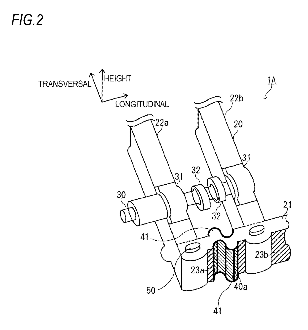
[0037]Further, in a cylinder head structure 1B for an internal combustion engine shown in FIG. 3, the flexible structure 40 (40a in FIG. 3) is configured as a slit-shaped structure, in which at least one slit 42 cut from a lower surface or an upper surface of the wall surfaces 23 in the height direction of the longitudinal frames is provided on a part of the at least one of the wall surfaces 23. The slit-shaped structure can be easily formed, for example, by cutting in the height direction of the cylinder head 10 or the like. Also, according to this configuration, the flexible structure 40 can be formed on the longitudinal frame 21 of the cam carrier 20 by a relatively simple processing, such as cutting, and also can be applied to existing engines.

[0038]The detailed specification of the slit-shaped structure 40, such as a shape and dimensions, is set on the basis of an amount of relative displacement between the cylinder head 10 and the cam carrier 20 under an overrunning condition...


PUM


Abstract

A cam carrier includes a pair of longitudinal frames provided parallel to an axial direction of a camshaft and a plurality of transversal frames connected to the pair of longitudinal frames to be spaced from each other and supporting the camshaft via cam bearings. A flexible structure suppressing amounts of change in a relative position and an inclined angle of the cam bearings relative to the camshaft due to a thermal expansion is provided on at least one of wall surfaces of the longitudinal frames, the wall surfaces being located between adjacent transversal frames.

Description

TECHNICAL FIELD[0001]The present disclosure relates to a cylinder head structure for an internal combustion engine and an internal combustion engine, in which a monolithic cam carrier is placed on a top of a cylinder head.BACKGROUND ART[0002]In general, most of internal combustion engines, such as diesel engines, are configured as a multi-cylinder engine provided with a plurality of cylinders. In a case where an OHC (overhead cam carrier) is employed for a valve mechanism in the multi-cylinder engine, multi-cylinder engine includes a camshaft having a plurality of cams for opening and closing an intake valve and an exhaust valve arranged on an upper portion of the inside of each cylinder, and the camshaft is rotatably supported by a cam carrier provided on the top of a cylinder head.[0003]In the multi-cylinder OHC engine, the cam carrier includes a pair of longitudinal frames provided parallel to an axial direction of the camshaft and a plurality of transversal frames connected to t...

Claims


Application Information

Patent Timeline
IPC IPC(8): F01L1/053
CPCF01L1/053F02F1/24F02F2001/244F01L2001/0535F01L2001/0476F01L2810/04F01L1/04
Inventor HIRUKAWA, KOUJI
Owner ISUZU MOTORS LTD
Why Eureka
Try Eureka