Method for making an abrasion resistant conductive film and gasket

Inactive Publication Date: 2005-06-07
SCHLEGEL SYST
View PDF8 Cites 21 Cited by
  • Summary
  • Abstract
  • Description
  • Claims
  • Application Information

AI Technical Summary

Benefits of technology

[0015]In use, the gasket is disposed in the gap between adjacent metal surfaces of the shielded housing. At least one of these surfaces bears against the peaks on the gasket surface to form a conductive circuit across the gap. Over time, relative movement of the adjacent metal surfaces may abrade the metal coating from the peaks on the surface of th

Problems solved by technology

Over time, relative movement of the adjacent metal surfaces may abrade the metal coating from the peaks on the surface of

Method used


Image

  • Method for making an abrasion resistant conductive film and gasket
  • Method for making an abrasion resistant conductive film and gasket
  • Method for making an abrasion resistant conductive film and gasket

Examples


Example

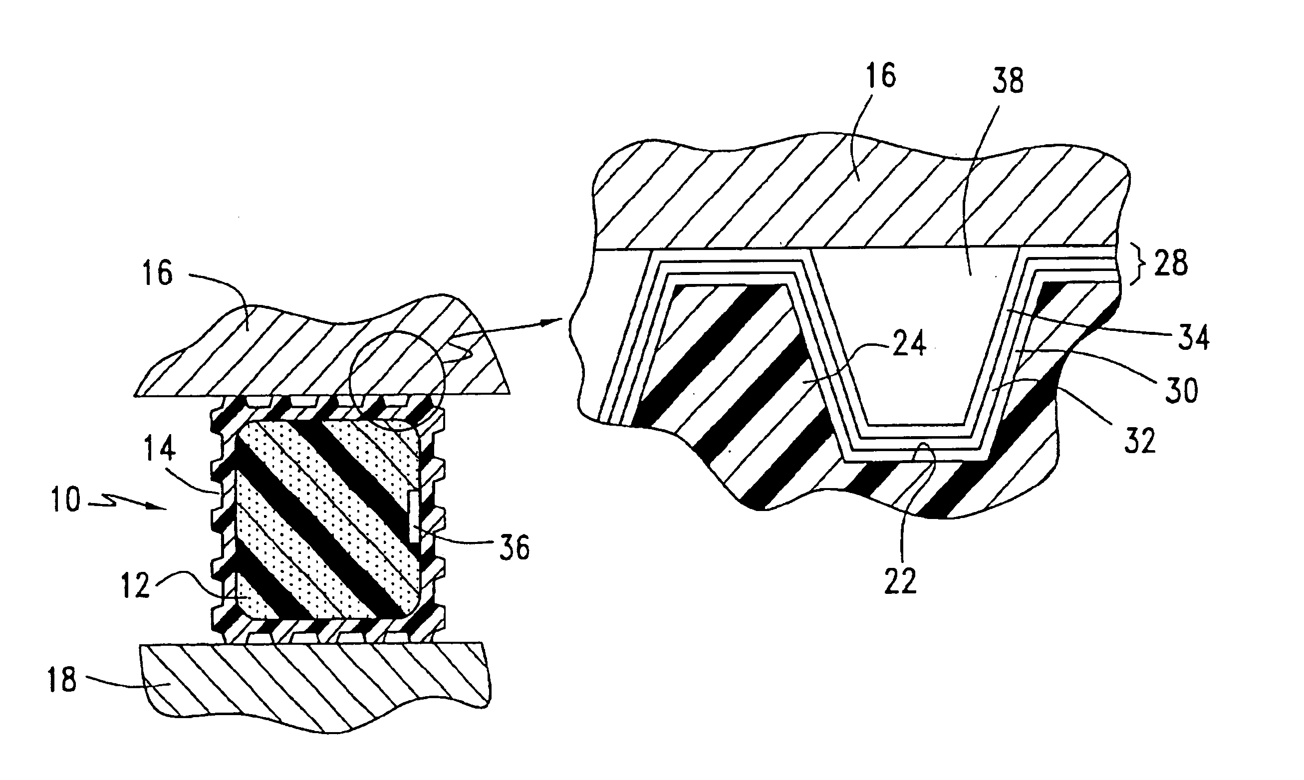
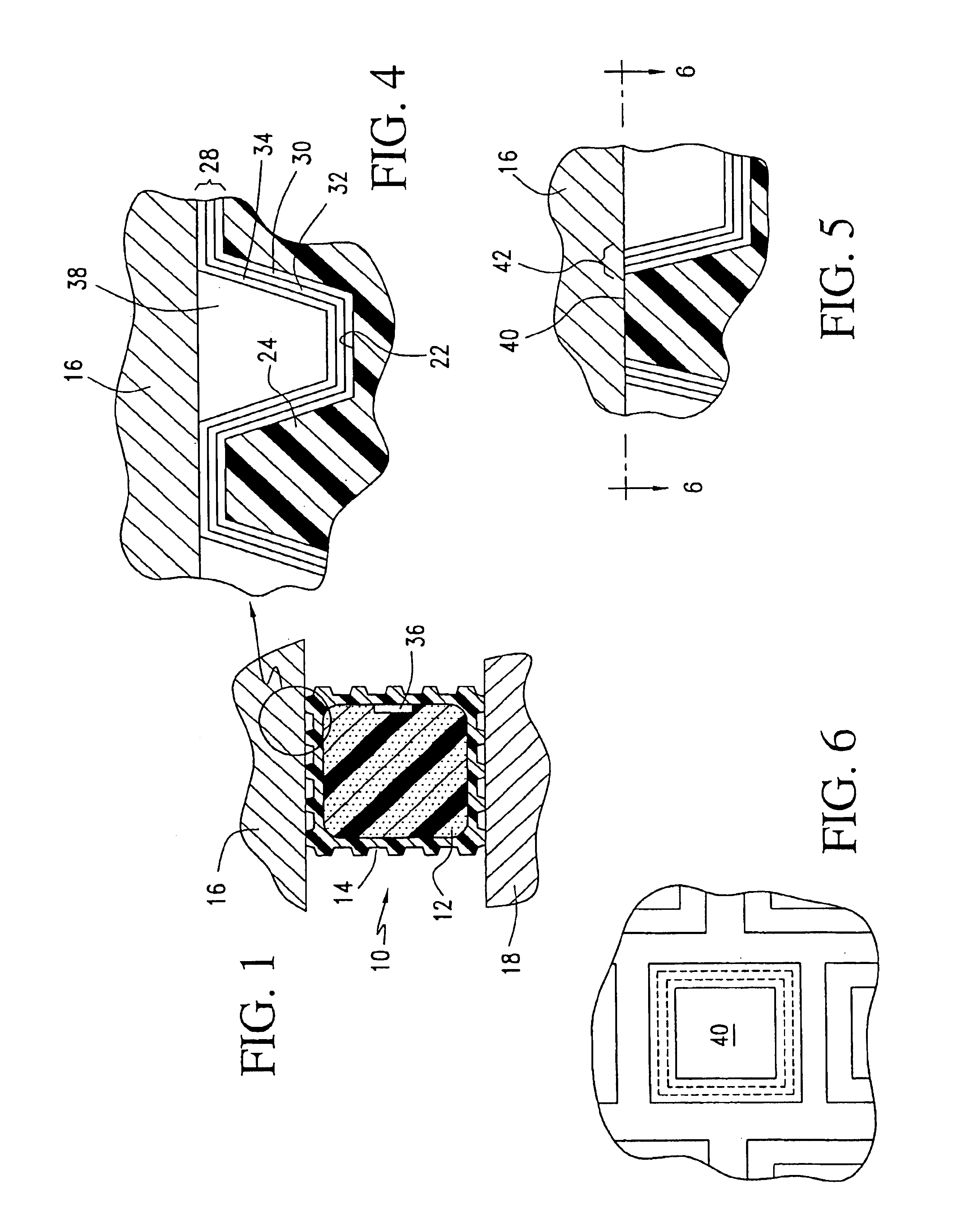
[0028]Referring to the drawings, FIG. 1 shows a conductive gasket of the present invention generally indicated at 10. The gasket comprises a continuously molded foam core 12, which is resilient and compliant over a range of temperatures and which preferably exhibits good compression set characteristics such that the material will “spring back” after repeated compression and decompression and even after long periods of compression. For example, a suitable material for core 12 is closed cell urethane foam.

[0029]Surrounding the core 12 is a sheath 14. The sheath preferably is composed of a polymeric material, as set out herein below, that is metalized to render the sheath conductive. The gasket 10, when positioned between adjacent metal surfaces 16,18 provides a conductive path between the surfaces to form an EMI shield.

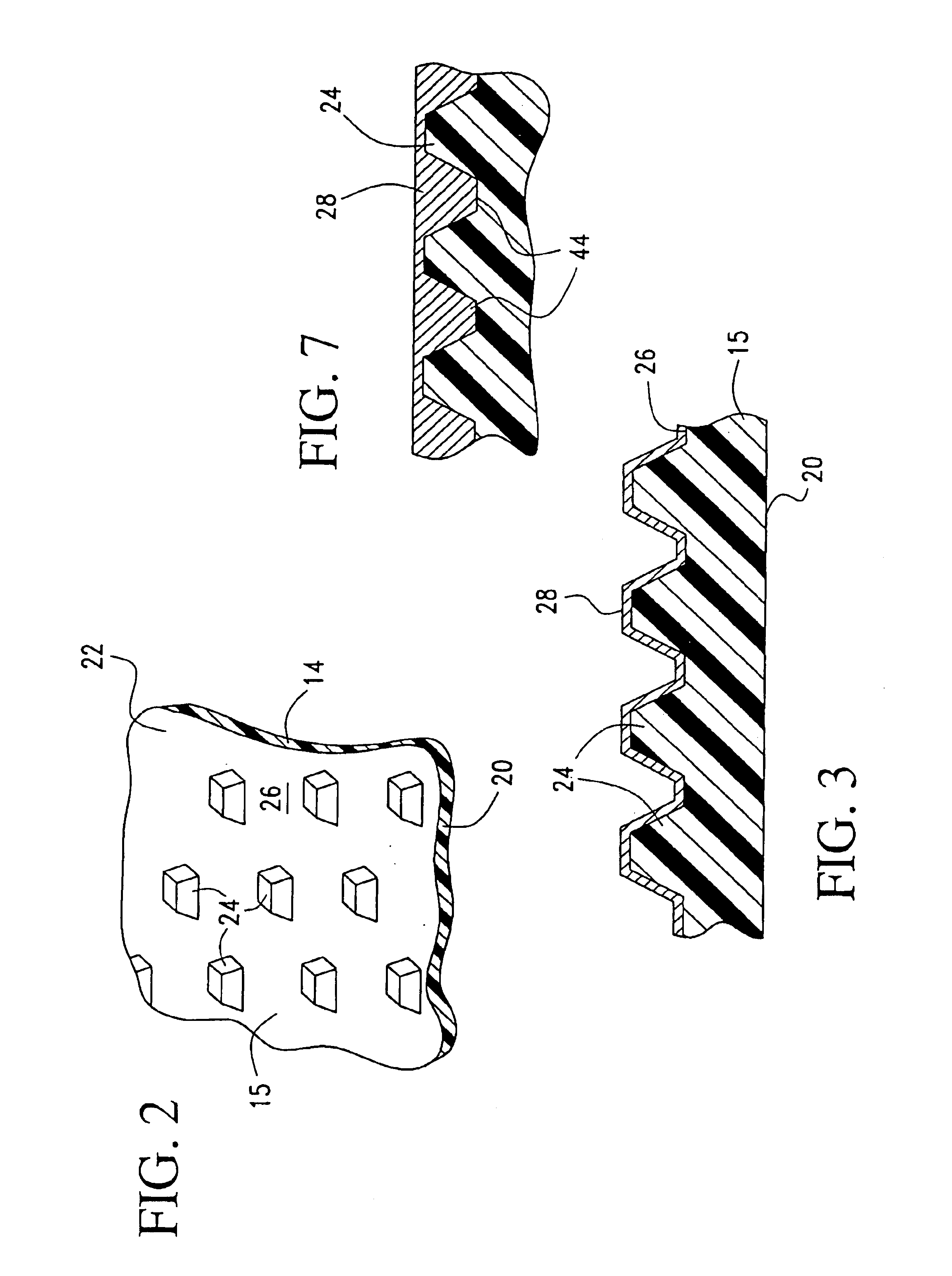
[0030]As seen in FIG. 2, the sheath 14 is composed of a polymeric film 15 having a reverse side 20 and an obverse side 22. The polymeric film may be formed of any suita...


PUM

PropertyMeasurementUnit
Electrical conductoraaaaaaaaaa
Abrasion resistanceaaaaaaaaaa
Resilienceaaaaaaaaaa

Abstract

A method for making a conductive gasket for use in apparatus to block the exit or entry of electromagnetic interference (EMI) between adjacent metal surfaces of the apparatus. The gasket is formed at least in part by a polymeric film having an outward facing surface embossed so as to provide a plurality of peaks distributed over the surface. A metal is coated, by vapor deposition, onto the surface so as to over lie the peaks.

Description

CROSS REFERENCE TO RELATED APPLICATIONS[0001]This application is a division of Ser. No. 09 / 805,324 filed Mar. 13, 2001, now U.S. Pat. No. 6,541,698.TECHNICAL FIELD[0002]The present invention relates to a method for making an abrasion resistant conductive film and more particularly to such a film having utility as a component of a conductive gasket for electrical apparatus to block the entry or exit of electromagnetic interference (EMI) and radio frequency interference (RFI) through openings in the apparatus.BACKGROUND OF THE INVENTION[0003]Many modern electronic devices emit or are sensitive to electromagnetic interference (EMI) at high frequencies. Electromagnetic interference is understood to mean undesired conducted or radiated electrical disturbances from an electric or electronic apparatus, including transients, which can interfere with the operation of other electrical or electronic apparatus. Such disturbances can occur anywhere in the electromagnetic spectrum. Radio frequenc...

Claims


Application Information

Patent Timeline
IPC IPC(8): H05K9/00B32B15/08H01B5/14F16J15/12
CPCH05K9/0015Y10S277/92Y10T29/49126Y10T29/49155Y10T29/49128
Inventor MISKA, STANLEY R.
Owner SCHLEGEL SYST
Why Eureka
Try Eureka