Compressor and hydrogen station

Pending Publication Date: 2022-04-21
KOBE STEEL LTD
View PDF9 Cites 1 Cited by
  • Summary
  • Abstract
  • Description
  • Claims
  • Application Information

AI Technical Summary

Benefits of technology

The aim of this patent is to prevent the wear of piston rings in a piston that has two groups of piston rings.

Problems solved by technology

It is considered that damage to the piston rings is cause by an increase in a load applied to the piston rings.
This increases the load applied to the piston rings and causes damage.
Along with this fluctuation, the load on the piston ring groups may increase and wear of the piston rings may be accelerated.

Method used


Image

  • Compressor and hydrogen station
  • Compressor and hydrogen station
  • Compressor and hydrogen station

Examples


first embodiment

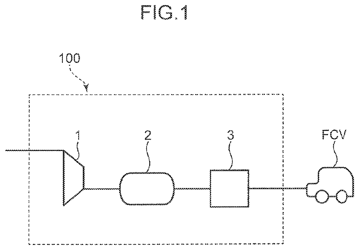
[0021]To begin with, a configuration of a hydrogen station 100 according to a first embodiment will be described with reference to FIG. 1. The hydrogen station 100 is a facility for replenishing a fuel cell vehicle (FCV) with a hydrogen gas as fuel. As shown in FIG. 1, the hydrogen station 100 includes a compressor 1 for compressing a hydrogen gas, an accumulator 2 for storing the high-pressure hydrogen gas compressed by the compressor 1 and then discharged from the compressor 1, and a dispenser 3 for receiving supply of the high-pressure hydrogen gas from the accumulator 2 and supplies the high-pressure hydrogen gas to a demand destination such as a fuel cell vehicle.

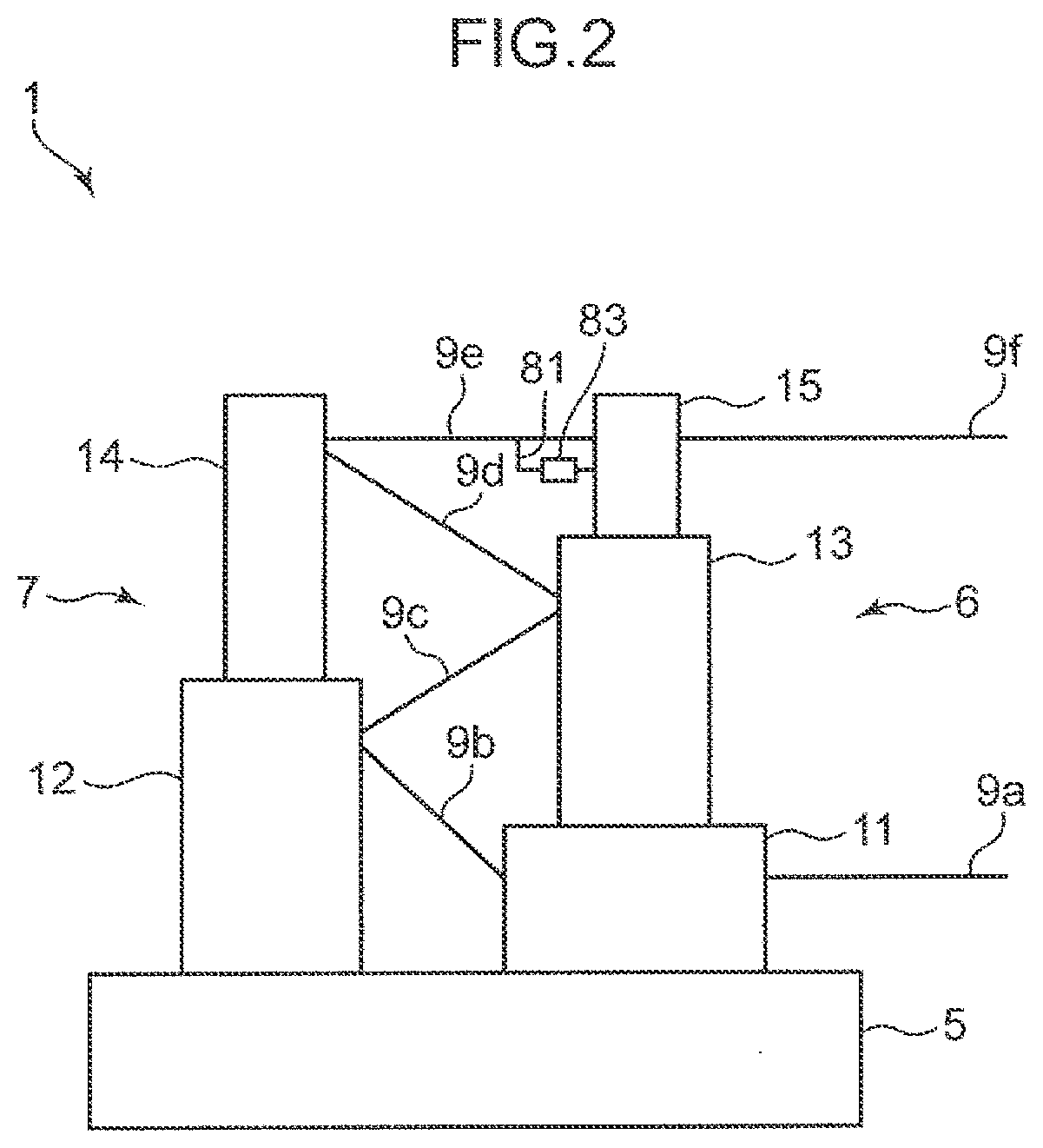
[0022]Next, a configuration of the compressor 1 will be described with reference to FIGS. 2 to 4. As shown in FIG. 2, the compressor 1 includes a plurality of compression stages (first to fifth compression stages 11 to 15) and a drive mechanism 5 that drives the plurality of compression stages 11 to 15. Each of the fiv...

second embodiment

[0054]Next, a compressor according to a second embodiment will be described. The compressor according to the second embodiment is basically similar to the compressor 1 according to the first embodiment, but differs in a configuration of a volume expansion unit. Only differences from the first embodiment will be described below.

[0055]FIG. 5 is a diagram schematically showing a configuration of a leak line 81a in the second embodiment. As shown in FIG. 5, the leak line 81a includes a volume expansion unit 83a connected to a piping part 82, and the volume expansion unit 83a includes a meandering pipe. The volume expansion unit 83a has a length in a range 84 of a predetermined distance longer than the length of the linear piping part 82 in the same distance range 84. Therefore, the volume in the range 84 is larger than the volume of the piping part 82 in the same range 84. That is, when the volume expansion unit 83 is compared with the piping part 82, the volume expansion unit 83 is lar...

third embodiment

[0056]Next, a compressor according to a third embodiment will be described. The compressor according to the third embodiment is basically similar to the compressor 1 according to the first embodiment, but differs in a configuration of a volume expansion unit. Only differences from the first embodiment will be described below.

[0057]FIG. 6 is a diagram schematically showing a configuration of a leak line 81b in the third embodiment. As shown in FIG. 6, the leak line 81b includes a volume expansion unit 83b connected to a piping part 82, and the volume expansion unit 83b includes a pipe formed in a spiral shape. The volume expansion unit 83b has a length in a range 84 of a predetermined distance longer than the length of the linear piping part 82 in the same distance range 84. Therefore, the volume in the range 84 is larger than the volume of the piping part 82 in the same range 84. A first piping part 82a is connected to one end of the volume expansion unit 83b, and a second piping pa...


PUM


Abstract

A cylinder in a compression stage is provided with a first cooling channel through which a cooling fluid for absorbing heat generated between the cylinder and a first piston ring group flows, a second cooling channel through which a cooling fluid for absorbing heat generated between the cylinder and a second piston ring group flows, and a through hole penetrating a side wall of the cylinder in an intermediate part between the first cooling channel and the second cooling channel A hydrogen gas leaking from a compression chamber to the intermediate part through between the cylinder and a piston and then guided to a leak line. The leak line includes a piping part and a volume expansion unit in which volume in a predetermined distance range is larger than volume of the piping part at the same distance range as the predetermined distance range.

Description

FIELD OF THE INVENTION[0001]The present invention relates to a compressor and a hydrogen station including the compressor.BACKGROUND ART[0002]Conventionally, a reciprocating compressor configured to reciprocate a piston in a cylinder to compress gas in a compression chamber of the cylinder has been known. In this compressor, a plurality of piston rings is installed on a piston outer peripheral surface such that the piston rings are aligned in an axial direction of the cylinder. This prevents the compressed gas obtained in the compression chamber from leaking through a gap between the piston outer peripheral surface and the cylinder inner peripheral surface.[0003]For example, in a reciprocating compressor disclosed in Japanese Patent No. 5435245, a large number of piston rings divided into two piston ring groups are installed on a piston outer peripheral surface. The compressor disclosed in Japanese Patent No. 5435245 is provided with a gas introduction unit connected to an intermedi...

Claims


Application Information

Patent Timeline
IPC IPC(8): F04B39/06
CPCF04B39/06F04B25/02F04B25/005F04B39/064
Inventor OTSUKA, TOMOHIROKANEI, NAOFUMI
Owner KOBE STEEL LTD
Why Eureka
Try Eureka