
Method for magnetic resonance imaging

Active Publication Date: 2015-10-01
ALBERT LUDWIGS UNIV FREIBURG
View PDF5 Cites 11 Cited by
  • Summary
  • Abstract
  • Description
  • Claims
  • Application Information

AI Technical Summary

Benefits of technology

The patent describes a method for getting a high-quality image by iteratively minimizing a cost function using a descent algorithm. This approach helps to improve the overall quality of the image and make it look better.

Problems solved by technology

Off-resonance effects and technical imperfections may lead to spatial phase variation in the acquired MR image, which destroys the conjugate symmetry of k-space.
In all above methods, reconstructed image phase was directly replaced by the estimated phase, which may be inaccurate in some regions with rapid phase variation.
Significant reconstruction errors exist in regions with poor phase estimation in these methods with ‘direct’ phase replacement.

Method used


Image

  • Method for magnetic resonance imaging
  • Method for magnetic resonance imaging
  • Method for magnetic resonance imaging

Examples


Embodiment Construction

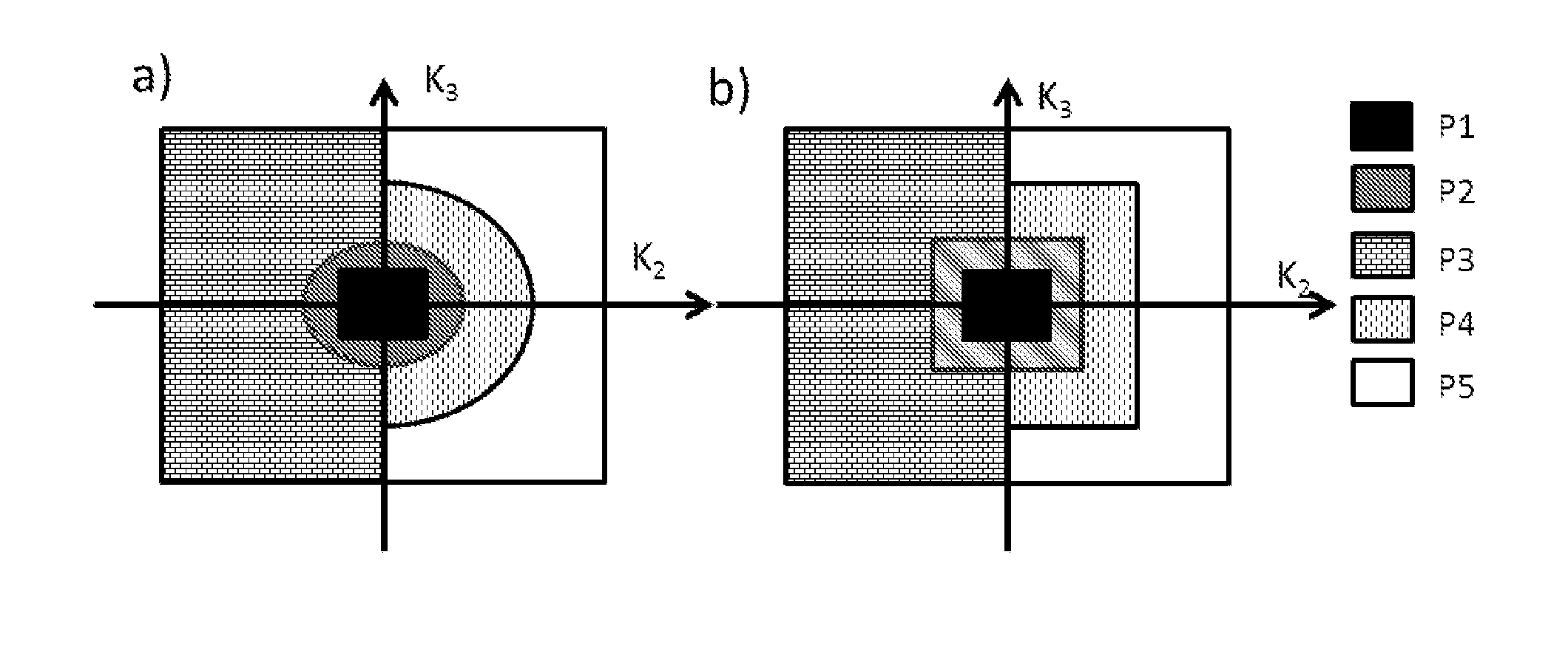
[0061]In preferred embodiments of the present invention, the shape of the subsets of k2-k3 plane is rectangular. This is compatible with k-space regular undersampling, and the missing data are efficiently reconstructed using algorithm in Reference [7].

[0062]In an alternative embodiment of the invention, the shape of the subsets of k2-k3 plane is elliptical. Here, image phase is efficiently estimated with a limited amount of acquired k-space data.

[0063]In a further embodiment of the invention, wherein the estimate of the phase PR is taken from the reconstructed image by using only the symmetrically acquired data in Part 1 and Part 2 in k2-k3 plane. This variant of the method according to the present invention is simple and direct, and provides sufficient accuracy in regions with slow phase variation.

[0064]In another class of embodiments of the invention, the weighting map W is set to the magnitude of the intermediate solution x. The accuracy of the image phase estimation is dependent...


PUM


Abstract

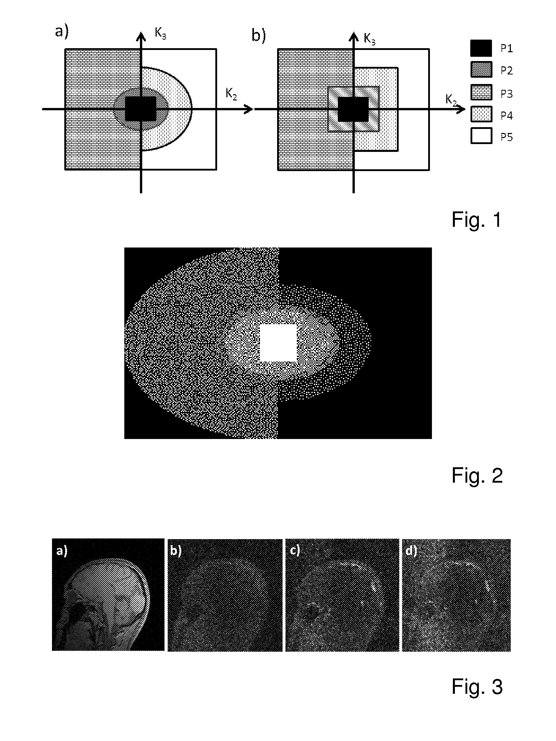
A method is presented for accelerating magnetic resonance imaging. In 3D MRI, the k-space in the phase encoding plane is divided into two symmetric parts and three asymmetric parts. Different sampling densities are applied in different parts. Images are reconstructed by iteratively minimizing a cost function when random sampling is applied in each part. A phase constraint term is added into the cost function to improve the quality of the reconstruction by exploiting the conjugate symmetry of k-space.

Description

[0001]This application claims Paris convention priority from EP 14 162 404.9 filed Mar. 28, 2014 the entire disclosure of which is hereby incorporated by reference.BACKGROUND OF THE INVENTION[0002]The present invention relates to a magnetic resonance imaging method for the acquisition of a three-dimensional dataset, where spatial encoding by three mutually orthogonal magnetic field gradients is performed such, that signal is readout under a read-gradient in one spatial direction k1 and spatial encoding in the other two spatial directions k2 and k3 is performed by applying phase encoding gradients in the other two spatial directions prior to signal acquisition and data acquisition is performed in a sequential manner such that at each acquisition step signal is acquired under the said readout gradient, but with different combinations of the two phase encoding gradients.[0003]A method of this type is known as 3DFT (or volume) imaging described in Reference [0] M. Bomans, K. Hohne, G. L...

Claims


Application Information

Patent Timeline
IPC IPC(8): G06T11/00
CPCG06T11/008G06T2207/10088G06T2207/10004G01R33/4822G01R33/4826G01R33/561G01R33/5611
Inventor LI, GUOBINZAITSEV, MAXIMHENNIG, JUERGEN
Owner ALBERT LUDWIGS UNIV FREIBURG
Learn More