Multi-Function Wire Stripping Hand Tool and Kit and Method For Using Same

Active Publication Date: 2015-10-01
ANDERSON WAYNE +1
View PDF20 Cites 3 Cited by
  • Summary
  • Abstract
  • Description
  • Claims
  • Application Information

AI Technical Summary

Benefits of technology

[0028]Still another aspect of the present invention is to provide a wire stripping device disposed longitudinally within the handle of the multi-function hand tool and having outwardly flared openings for guiding the wire into the wire stripping device together with the actuator, where the actuator is spring biased longitudinally to maintain the movable blade in a retracted and open position when not depressed. Optionally, the actuator has a rounded dome

Problems solved by technology

For larger gauge wires, where the insulation layer is typically thicker and more rigid, it is more difficult to remove with hand tools.
Unfortunately, damage may be caused to the underlying conductor when penetrating the insulation layer with a manual cutting tool (such as a wire cutter or knife) due to imprecise cutting depth control.
Rather elaborate tools have been previously provided for stripping the insulation from the wire, but these tools can be relatively expensive and have only the single purpose of removing insulation.
Thus, such tools are burdensome to carry and occupy a considerable space area within the tool box or wherever it is carried.
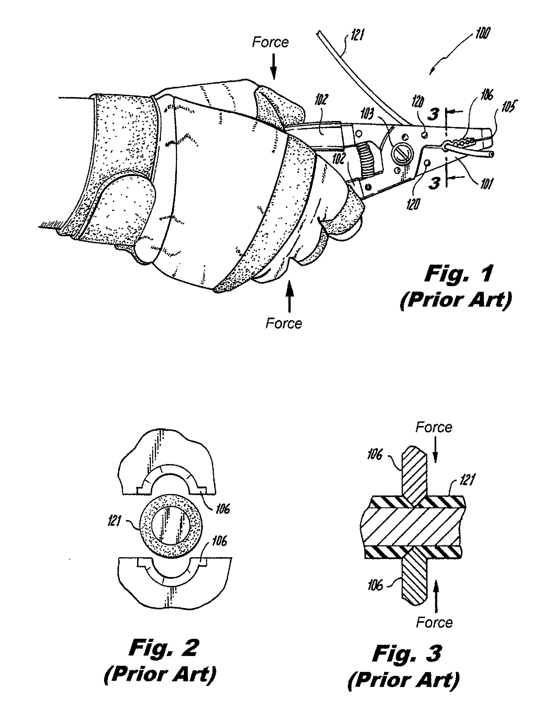
Unfortunately such scissor-action types require a user to pull against the axis of the wire to strip the outer insulation and this creates a stress on a user's forearm, wrist, hand, and even upper arm.
Typically, after much stripping (by a professional installer) a sort o

Method used


Image

  • Multi-Function Wire Stripping Hand Tool and Kit and Method For Using Same
  • Multi-Function Wire Stripping Hand Tool and Kit and Method For Using Same
  • Multi-Function Wire Stripping Hand Tool and Kit and Method For Using Same

Examples


Embodiment Construction

[0061]As required, a detailed illustrative embodiment of the present invention is disclosed herein. However, techniques, systems, compositions and operating structures in accordance with the present invention may be embodied in a wide variety of sizes, shapes, forms and modes, some of which may be quite different from those in the disclosed embodiment. Consequently, the specific structural and functional details disclosed herein are merely representative, yet in that regard, they are deemed to afford the best embodiment for purposes of disclosure and to provide a basis for the claims herein which define the scope of the present invention.

[0062]Reference will now be made in detail to several embodiments of the invention that are illustrated in the accompanying drawings. Wherever possible, same or similar reference numerals are used in the drawings and the description to refer to the same or like parts or steps. The drawings are in simplified form and are not to precise scale. For pur...


PUM


Abstract

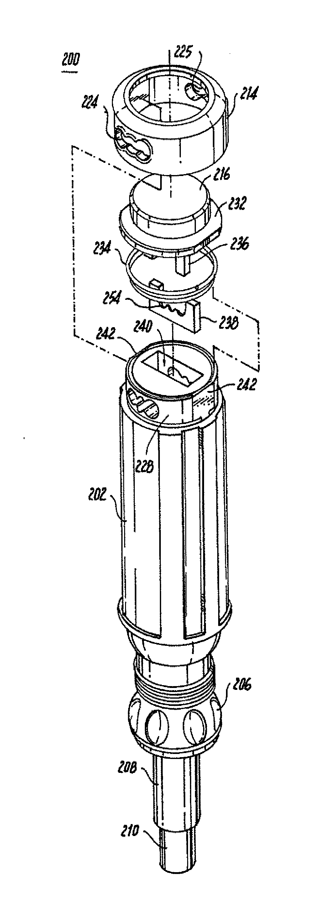
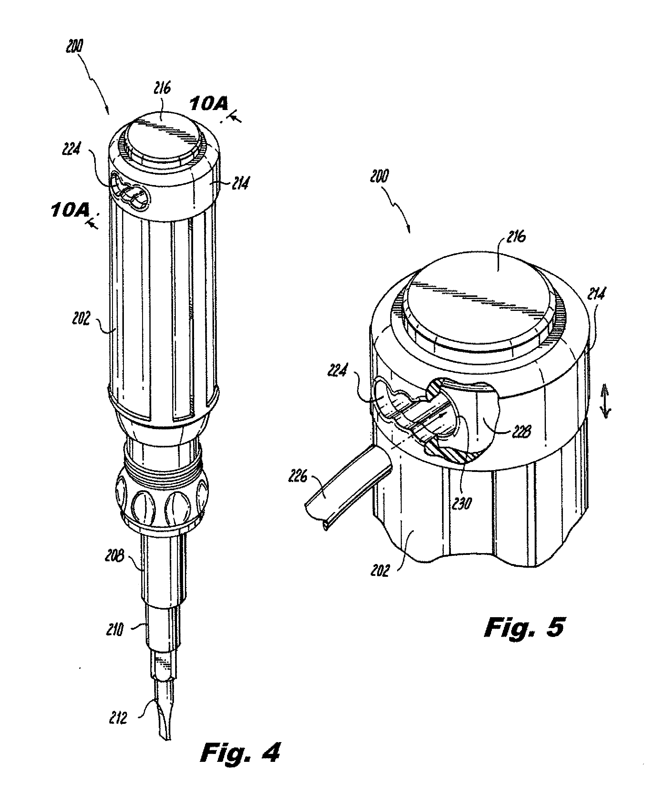
A multi-function wire stripping hand tool generally for electricians that has a wire stripping system for a controlled cut and strip of the insulation from a wire. The tool includes an elongated body member having a longitudinal cavity and a transverse opening therein which communicates with the longitudinal cavity and one end of the body member. A stationary cutting blade is disposed in the inner end of the longitudinal cavity, and a movable cutting blade is movably mounted within an upper end of the longitudinal cavity. A spring is disposed between and engaged with a push button actuator so as to urge the movable blade to an open and retracted position. The wire stripping system is engaged with a handle region of the hand tool, and permits stripping in a direction that is perpendicular a longitudinal axis of the multi-function hand tool. The wire stripping system may be used from either side of the hand tool, and may be provided with a plurality of first and second operably engaged housings for securing a number of tool bit members.

Description

CROSS REFERENCE TO RELATED APPLICATIONS[0001]This application relates to and claims priority from U.S. Prov. Ser. No. 61 / 972,757 filed Mar. 31, 2014, the entire contents of which are incorporated herein by reference.FIGURE SELECTED FOR PUBLICATION[0002]FIG. 4BACKGROUND OF THE INVENTION[0003]1. Field of the Invention[0004]The present invention relates generally to hand tools and more particularly a device for stripping the insulation cover from an insulated wire such as those normally employed for transmitting electrical energy in a building with an improved ergonomic function. More particularly, the present invention relates to an electrical installer hand tool having a convenient and easy to use wire stripping mechanism for stripping an insulation layer from a wire during use of the hand tool that provides for an improved stripping-motion by a user and results in reduced hand and forearm stress and correspondingly to reduced risk of long term injury through repetitive use created b...

Claims


Application Information

Patent Timeline
IPC IPC(8): H02G1/12B25F1/02
CPCB25F1/02H02G1/1214B25H3/02
Inventor ANDERSON, WAYNEANDERSON, WARREN
Owner ANDERSON WAYNE
Why Eureka
Try Eureka