Three-dimensional molding equipment

a three-dimensional molding and equipment technology, applied in auxillary shaping apparatus, manufacturing tools, additive manufacturing processes, etc., can solve the problems of high-energy radiation, shorten molding time, and need to be concentrated, and achieve the effect of improving molding efficiency

Active Publication Date: 2015-10-08
MATSUURA MACHINERY
View PDF2 Cites 56 Cited by
  • Summary
  • Abstract
  • Description
  • Claims
  • Application Information

AI Technical Summary

Benefits of technology

[0010]Since the present invention is thus configured, the plurality of divided regions can be simultaneously sintered, thereby achieving to improve molding efficiency.

Problems solved by technology

With this configuration, there are effects that a radiated location of the light beam or the electron beam can be moved fast by the galvano scanner device, and there is an effect of shortening molding time.
However, to sinter the powder material, high-energy radiation is required and the light beam or the electron beam is needed to be concentrated.
Since the radiation diameter is extremely small as described above, there is a problem in that it takes a extremely long time to manufacture a relatively large molding object even in the case of using the galvano scanner device.
However, according to this related art, control tends to be complicated because the radiation diameter is needed to be changed and there are number of scanning patterns executed by the single galvano scanner device.

Method used


Image

  • Three-dimensional molding equipment
  • Three-dimensional molding equipment
  • Three-dimensional molding equipment

Examples


examples 1

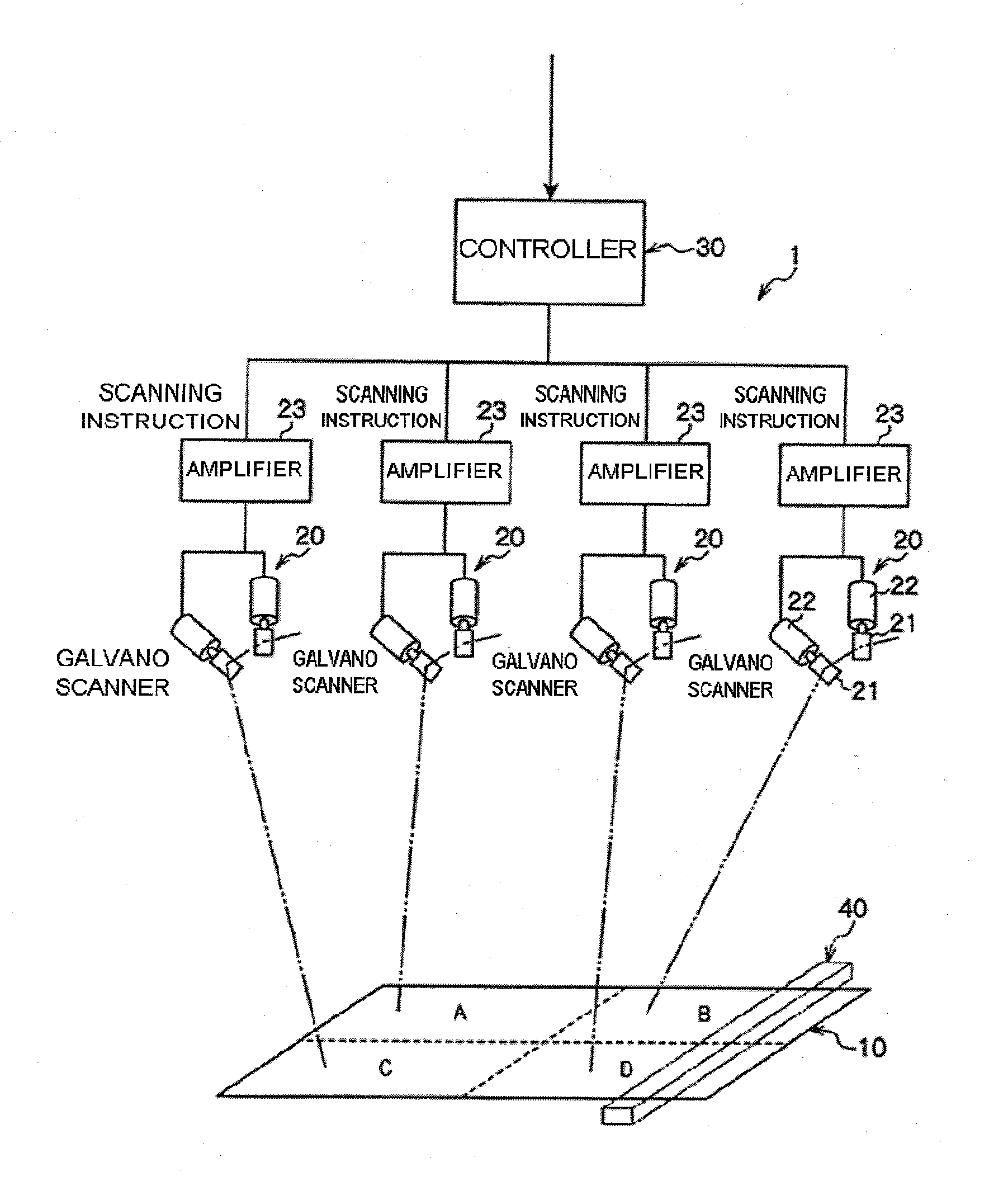
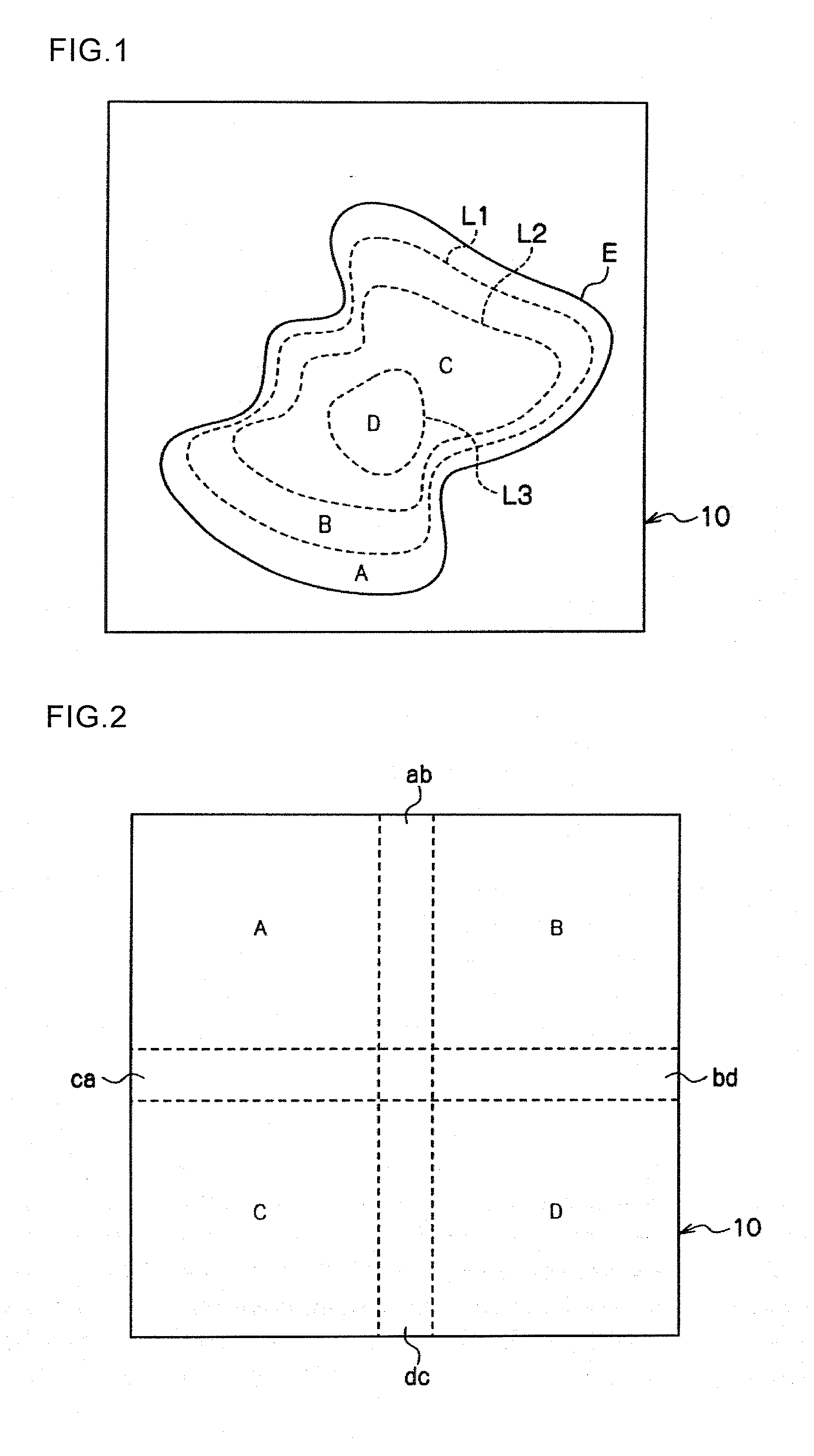
[0060]According to a first embodiment illustrated in FIG. 1, a plurality of boundary lines L1, L2 and L3 each having an endless ring shape is formed on an upper surface of each of the powder layers, separated inward from a contour of a region to be molded E by different distances. The plurality of regions divided by these boundary lines L1, L2 and L3 is defined as a plurality of divided regions A, B, C and D allocated with a plurality of light beam or electron beam scanning units 20 (In FIG. 1, illustration with molding parts Pa, Pb, Pc, and Pd is omitted).

[0061]Further, according to this embodiment, a radiation amount per unit area of the light beam or electron beam scanning unit 20 corresponding to a divided region close to the contour of the region to be molded E is controlled to be different from the radiation amount per unit area of the light beam or electron beam scanning unit 20 corresponding to a divided region close to a center portion of the region to be molded E.

[0062]Mor...

example 2

[0069]According to a second embodiment illustrated in FIG. 2, a plurality of the divided regions A, B, C and D are set, and two light beam or electron beam scanning units 20, 20 corresponding to two adjacent divided regions A and B (B and D, D and C, or C and A) are configured such that a radiated region of a light beam or an electron beam by one of the light beam or electron beam scanning units 20 overlaps with the radiated region of the light beam or the electron beam by the other light beam or electron beam scanning unit 20, at a portion close to a boundary of the two adjacent divided regions (In FIG. 2, illustration with molding parts Pa, Pb, Pc, and Pd is omitted).

[0070]In other words, as illustrated in FIG. 2, overlapped portions ab, bd, dc and ca in which the radiated regions of the light beam or the electron beam are overlapped are formed in the portion close to the boundary of the two adjacent divided regions A and B (B and D, D and C, or C and A).

[0071]Therefore, according...

example 3

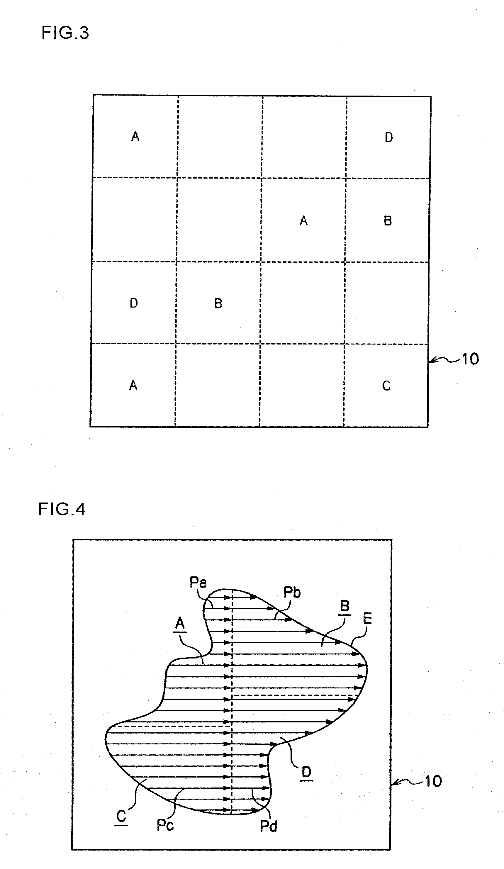
[0073]According to a third embodiment illustrated in FIG. 3, the number of divided regions used for manufacturing a three-dimensional shaped molding object is set larger than the number of light beam or electron beam scanning units 20 (In FIG. 3, illustration with molding parts Pa, Pb, Pc, and Pd is omitted).

[0074]A plurality of divided regions A, B, C and D, the number of which is larger than the number of the light beam or electron beam scanning units 20, is suitably allocated with the mentioned plurality of the light beam or electron beam scanning units 20 (four in an example in FIG. 3).

[0075]According to the example in FIG. 3, each of three divided regions A, two divided regions B, one divided region C, and two divided regions D is allocated with one of the light beam or electron beam scanning units 20. It should be noted that regions not indicated by the reference sign in FIG. 3 are not allocated with any of the light beam or electron beam scanning units 20.

[0076]Therefore, acc...


PUM

PropertyMeasurementUnit
radiation diameteraaaaaaaaaa
lengthaaaaaaaaaa
areaaaaaaaaaaa

Abstract

Three-dimensional molding equipment includes powder supply equipment configured to supply powder material and form a powder layer, and a light beam scanning unit configured to radiate a light beam to the powder layer and move a radiated location thereof, where a three-dimensional shaped molding object is manufactured by alternately repeating processes of forming the powder layer and sintering the powder layer with light beam radiation. A region used for manufacturing the three-dimensional shaped molding object is divided into a plurality of divided regions such that respective divided regions have an equal-length molding path which is to be a scanning route of the beam such as having unequal-length molding parts by a scanning route of the beam, and radiation is executed by a plurality of the light beam scanning units to the respective plurality of divided regions to improve molding efficiency.

Description

TECHNICAL FIELD[0001]The present invention relates to three-dimensional molding equipment that manufactures a three-dimensional shaped molding object by laminating and sintering powder material, and a method for manufacturing the three-dimensional shaped molding object.RELATED ART OF THE INVENTION[0002]According to this kind of invention in related arts, a three-dimensional shaped molding object including a number of sintered layers is manufactured by repeating a process of supplying powder material from powder supply equipment to form a powder layer and a process of radiating a light beam or an electron beam to a predetermined region of the powder layer formed in the mentioned process to sinter the powder in the predetermined region.[0003]Meanwhile, in the above-described related arts, a galvano scanner device is used to radiate the light beam or the electron beam in most cases. For example, Patent Document 1 of JP 2005-336547 A discloses an invention in which a light beam or an el...

Claims


Application Information

Patent Timeline
Patent Type & Authority Applications(United States)
IPC IPC(8): B22F3/105B28B17/00B28B1/00
CPCB22F2003/1056B22F2003/1057B22F3/1055B33Y50/02B28B17/0081B33Y30/00B28B1/001B33Y10/00B29C64/153Y02P10/25B22F12/49B22F10/31B22F10/28B22F12/45
Inventor TAKEZAWA, YASUNORIMAEDA, TOSHIOKATO, TOSHIHIKOAMAYA, KOICHI
Owner MATSUURA MACHINERY
Why Eureka
Try Eureka