Supercharge Your Innovation With Domain-Expert AI Agents!

High pressure relief valve flow disruptor

a technology of pressure relief valve and flow disruptor, which is applied in the direction of transportation and packaging, functional valve types, turbine/propulsion fuel valves, etc., can solve the problem of valves being opened further

Active Publication Date: 2015-10-08
HAMILTON SUNDSTRAND CORP
View PDF2 Cites 3 Cited by
  • Summary
  • Abstract
  • Description
  • Claims
  • Application Information

AI Technical Summary

Benefits of technology

The patent text describes a fluid flow disruptor and a pressure relief valve assembly that combine to increase turbulence in a fluid flow, reducing the pressure load on a valve. The disruptor includes a base flange and a cap with at least one aperture, which directs the fluid flow in an axial direction through the cap and into the valve. The assembly also includes a pressure relief valve and a disruptor, which work together to decrease the axial momentum load on the valve. Overall, the technical effect of the patent is to increase the turbulence of the fluid flow, reducing the pressure load on the valve and improving the performance of the valve assembly.

Problems solved by technology

Although the pressure relief valve may open at the predetermined set pressure, the valve may experience a negative droop, which may cause the valve to open further when subjected to a pressure less than the set pressure.

Method used


Image

  • High pressure relief valve flow disruptor
  • High pressure relief valve flow disruptor
  • High pressure relief valve flow disruptor

Examples


Embodiment Construction

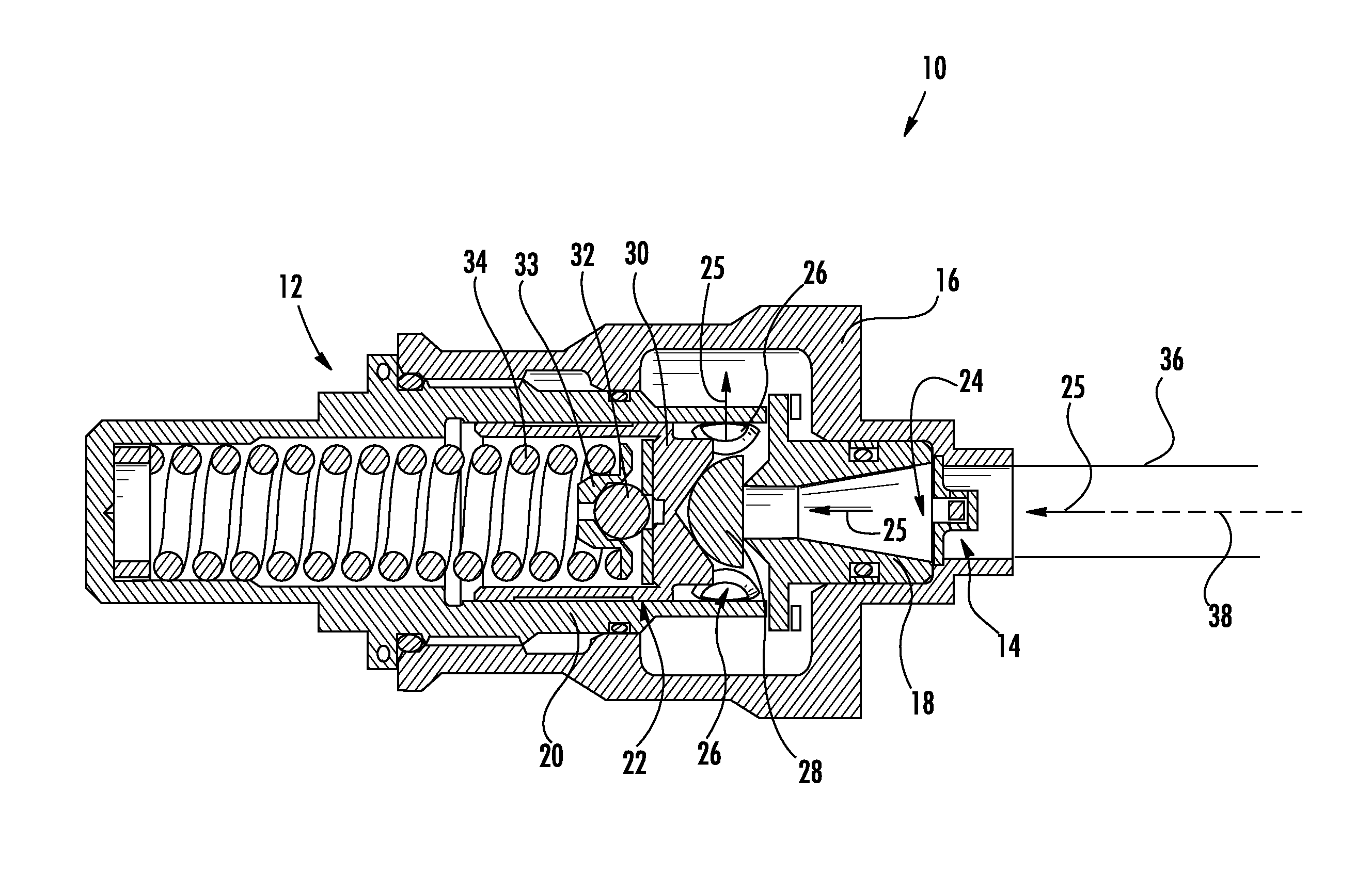
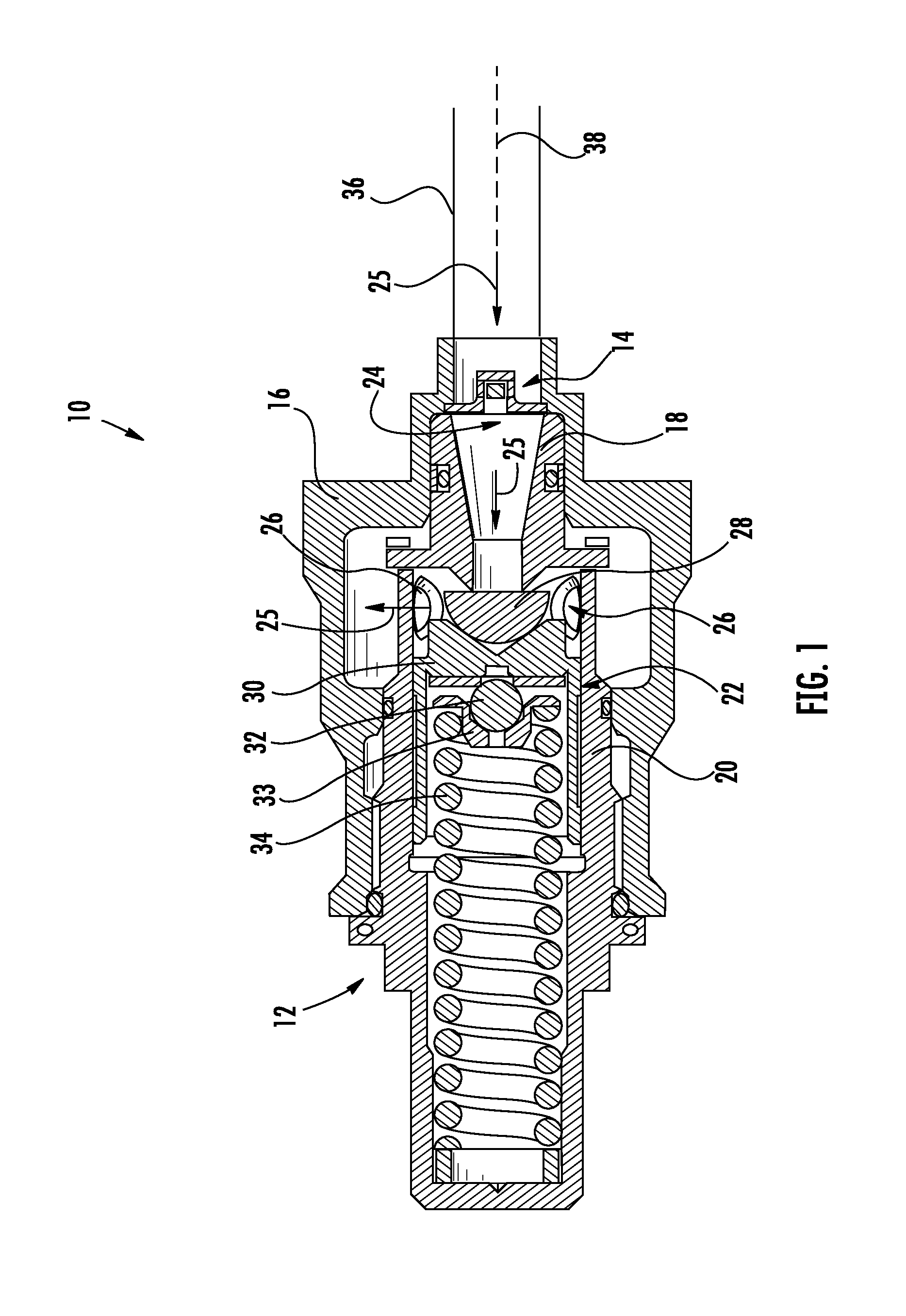
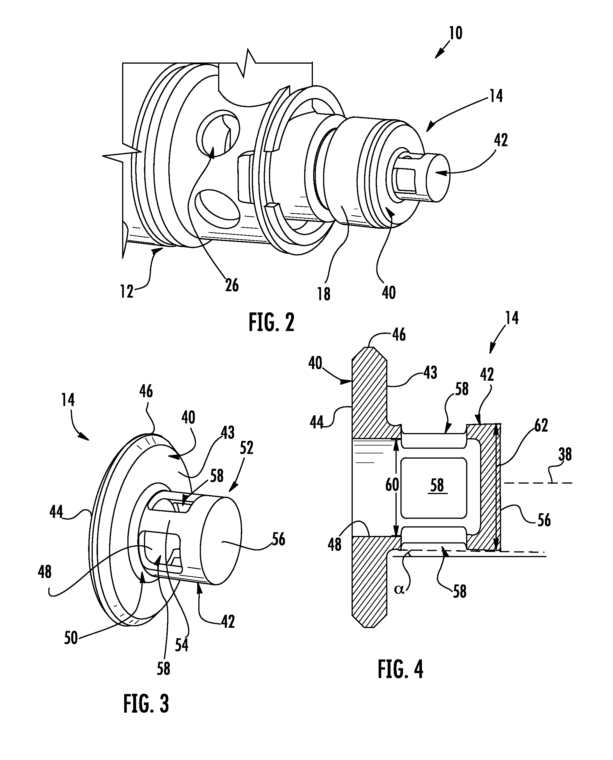
[0012]Described herein is a flow disruptor for a valve or other fluid flowing device. The flow disruptor changes the direction of an axially flowing fluid by forcing the fluid around components of the disruptor. This altered flow increases fluid turbulence, which results in the fluid flowing in a non-axial direction (e.g., increased fluid tangential velocity), which reduces fluid momentum forces in the axial direction that act on a valve downstream of the fluid flow disruptor.

[0013]FIGS. 1 and 2 illustrate an valve assembly 10 that includes a pressure relief valve (PRV) 12 and a flow disruptor 14. As shown in FIG. 1, valve assembly 10 may be arranged in a housing 16 with other valves (not shown). Although described herein in combination with a pressure relief valve, flow disruptor 14 may be coupled to various other fluid flowing devices. Moreover, PRV 12 is merely an example relief valve, and PRV 12 may have any suitable structure that enables assembly 10 to function as described he...


PUM


Abstract

In one aspect, a fluid flow disruptor is provided. The fluid flow disruptor includes a base flange having an outer diameter and an inner diameter, the base flange configured to couple to a valve, and a cap extending from the base flange. The cap includes a proximal end coupled to the base flange about the inner diameter, a distal end, and a sidewall extending between the proximal end and the distal end. At least one aperture is formed in the sidewall, and the fluid flow disruptor is configured to direct a fluid flowing in an axial direction to flow around the cap distal end, through the at least one aperture, and through the base flange inner diameter into the valve, to thereby increase a turbulence of the fluid to decrease an axial momentum load of the fluid acting on the valve.

Description

BACKGROUND OF THE INVENTION[0001]This disclosure generally relates to fluid flow disruptors, and more particularly, to fluid flow disruptors for pressure relief valves.[0002]Typically, a pressure relief valve is used to control or limit pressure buildup in a fluid transporting system. The pressure may be relieved by allowing the pressurized fluid to flow through the pressure relief valve to another portion of the system or even out of the system. The pressure relief valve may be designed or set to open at a predetermined set pressure to protect pressure vessels and other equipment from being subjected to pressures that exceed their design limits.[0003]Although the pressure relief valve may open at the predetermined set pressure, the valve may experience a negative droop, which may cause the valve to open further when subjected to a pressure less than the set pressure. The negative droop may be caused at least in part by fluid momentum forces acting on the valve. As such, the negativ...

Claims


Application Information

Patent Timeline
Patent Type & Authority Applications(United States)
IPC IPC(8): F16K17/04
CPCY10T137/7739F16K17/0433F16K17/04F16K47/08Y10T137/0497F16K17/048F02C7/232F16K11/07
Inventor RICKIS, AARON F.MAROCCHINI, FRANCIS P.
Owner HAMILTON SUNDSTRAND CORP
Features
  • R&D
  • Intellectual Property
  • Life Sciences
  • Materials
  • Tech Scout
  • Unparalleled Data Quality
  • Higher Quality Content
  • 60% Fewer Hallucinations
Learn More