
Firearm accessory mounting interface

a technology for mounting interfaces and accessories, applied in the field of firearms, can solve the problems of adding weight, difficult to install one of the many accessories receivable on the rails, and system installation may be difficult or complex, and achieve the effects of improving the firearm accessory mounting interface, reducing the weight of the weapon system, and being convenient to us

Active Publication Date: 2015-10-08
MAGPUL INDUSTRIES
View PDF12 Cites 36 Cited by
  • Summary
  • Abstract
  • Description
  • Claims
  • Application Information

AI Technical Summary

Benefits of technology

The present invention provides an improved firearm accessory mounting interface that is easy to use, adds minimal or no weight to a weapon system, is unlikely to snag, is unlikely to clog with mud and debris, and is comfortable to hold. The new interface is faster, easier to adapt to polymeric material processes, and results in greater part consistency than the prior art interfaces. The improved interface uses a three-part fastening system consisting of a screw, a nut, and an elongated slot. The elongated slot is designed to allow clearance of the second fastener when in an "open" position and prevent clearance once the second fastener has passed through and is turned to a "closed" or "locked" position. The first fastener can be turned, which in turn causes the second fastener to rotate and lock the second fastener. The first fastener can also pinch or squeeze the firearm accessory between itself and the firearm, locking it securely. The second fastener is a cammed fastener that can be inserted into the slot and mated with the first fastener to lock the accessory to the handguard. The second cammed fastener has parallel straight edges that prevent it from rotating more than 45 degrees to 135 degrees. The improvements provide a more reliable and comfortable mounting interface for firearm accessories.

Problems solved by technology

Most notably, they can be uncomfortable when grasped by a user's hands, they can snag on clothing, barbed wire, and other objects, they add weight to a weapon system, and under certain field conditions they may become clogged with dirt and other debris that make it difficult to install one of the many accessories receivable on the rails.
While this decreases weight (and the discomfort and other disadvantages) of having needless rails where the hand is to grip, it suffers from other disadvantages.
First, such systems may be difficult or complex to install.
Second, they may require custom modification of parts, such as drilling and tapping holes where needed.
Third, the attachment locations may be in limited locations due to the need to relocate fasteners such as threaded inserts (or may increase cost and weight by using an excessive number of fasteners).
A further significant disadvantage of systems having modular rails that may be mounted in various locations on the forearm or handguard of a rifle stock is the susceptibility to loosening.
If the mount for a rifle scope becomes loose, this can cause significant aiming errors.
However, the KEYMOD specifications also suffer from several disadvantages including more complex manufacturing.
The KEYMOD specification is also harder to implement in polymeric materials since it typically requires complex secondary machining operations rather than standard molding processes to form the keyhole apertures.

Method used


Image

  • Firearm accessory mounting interface
  • Firearm accessory mounting interface
  • Firearm accessory mounting interface

Examples


Embodiment Construction

[0087]With reference now to the drawings, the preferred embodiment of the firearm accessory mounting interface is herein described. It should be noted that the articles “a”, “an” and “the”, as used in this specification, include plural referents unless the content clearly dictates otherwise.

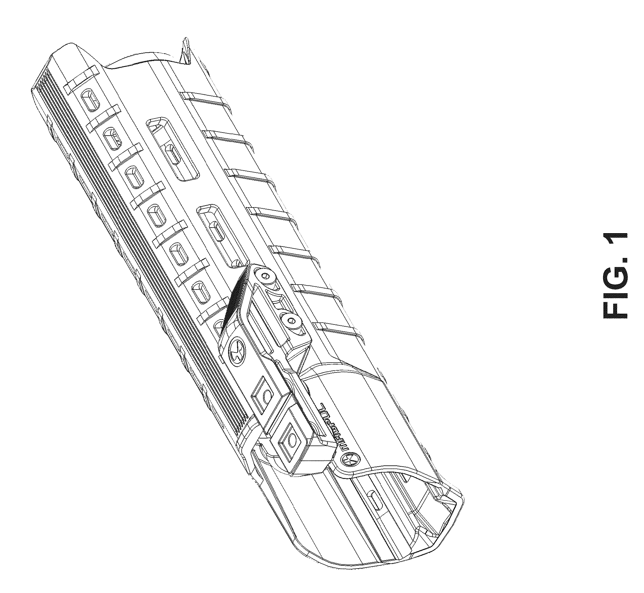
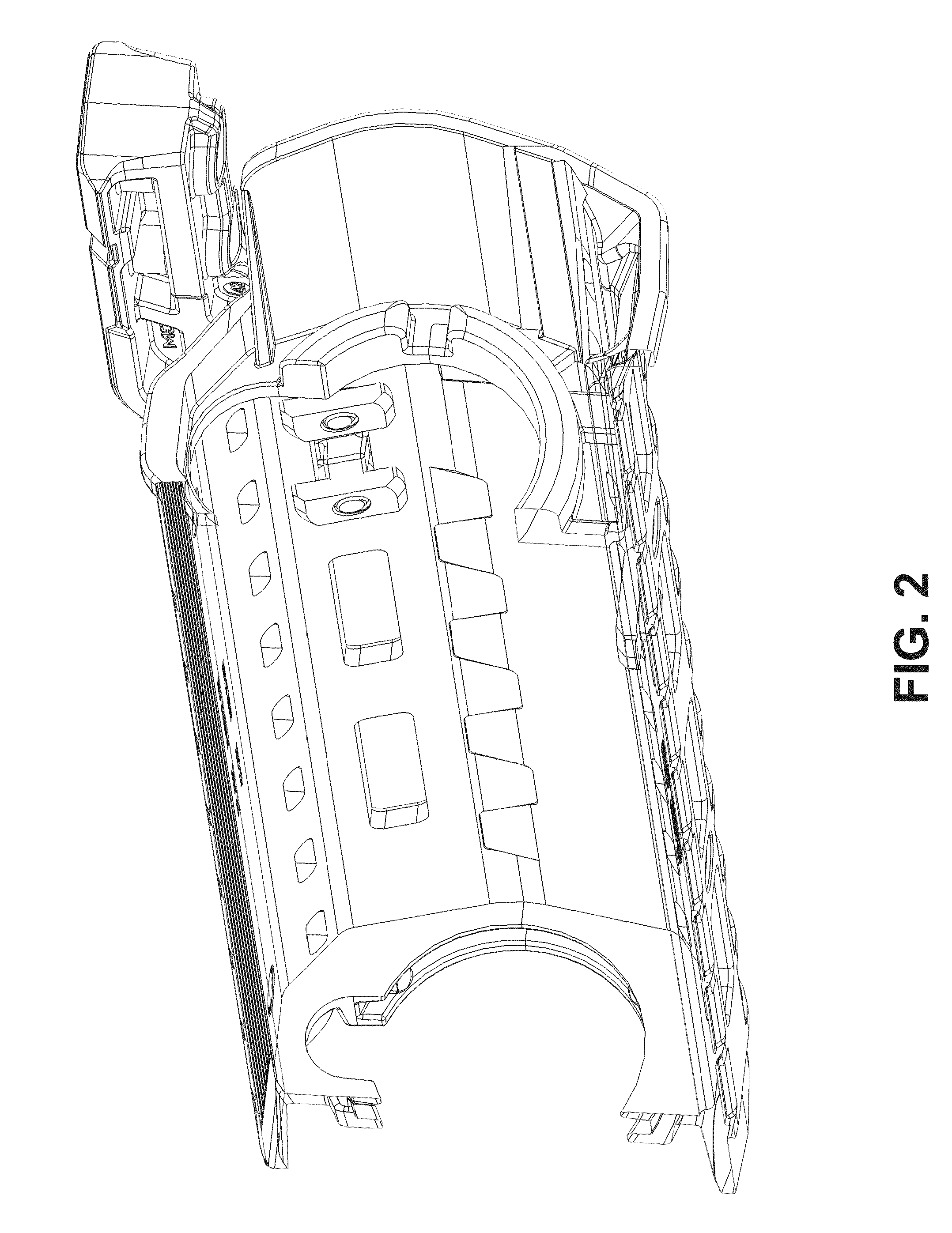
[0088]The improved firearm accessory mounting interface comprises three parts: a first elongated fastener (e.g., a screw or first cammed fastener), second fastener (e.g., a nut or a second cammed fastener), and an elongated slot. Embodiments of the entire interface as used on handguards can be seen in FIGS. 1-6. Embodiments of the interface as used on a portion of a firearm can be seen in FIGS. 7-14B. Embodiments of the second fastener can be seen in FIGS. 15-19, and 23A-33 and 48-55. Embodiments of the first elongated fastener and the second fastener can be seen in FIG. 28. Embodiments of the elongated slot as used in a handguard can be seen in FIGS. 1-6 and 20-21. Embodiments of a firearm acces...


PUM


Abstract

An improved firearm accessory mounting interface is herein disclosed. The interface can include one or more sets of first and second fasteners that interface through an elongated slot in a firearm in order to mount a firearm accessory to a firearm. The second fastener can be shaped and sized to clear the elongated slot and can, upon clearing the elongated slot, be pivoted to an oblique orientation relative to the elongated slot so that the second fastener cannot be retracted. The first fastener can continue to be turned thus drawing the first and second fasteners toward each other and locking the accessory to the firearm.

Description

PRIORITY[0001]The present application claims priority under 35 U.S.C. 120 to U.S. patent application Ser. No. 14 / 271,912, entitled, “FIREARM ACCESSORY MOUNTING INTERFACE”, and filed May 7, 2014, which claims priority under 35 U.S.C. 119(e) to U.S. Provisional Patent Application No. 61 / 974,968, entitled, “FIREARM ACCESSORY MOUNTING INTERFACE,” and filed Apr. 3, 2014, the entirety of these applications is incorporated herein by reference.FIELD OF THE DISCLOSURE[0002]The present invention relates to the field of firearms and more particularly relates to an improved firearm accessory mounting interface.BACKGROUND[0003]Modern firearms, in particular, military assault rifles, can be deployed for a number of combat missions such as sniper weapons and in close combat. They are commonly used for nighttime combat. All of these applications can require fitting a variety of telescopic sights, infrared sights, tactical lights, laser sighting modules, grenade launchers, bipods, grips and other ac...

Claims


Application Information

Patent Timeline
Patent Type & Authority Applications(United States)
IPC IPC(8): F41C23/16F41A23/08F41C23/02F41G1/00
CPCF41C23/16F41C23/02F41A23/08F41G1/00F41G11/004F41G11/001F41G11/003F41G11/005
Inventor MAYBERRY, MICHAEL T.BENNETT, WILLIAM BRADLEYROBERTS, TIMOTHY ERICLIPTAK, DUANENAKAYAMA, BRIAN L.
Owner MAGPUL INDUSTRIES
Learn More