System and method for determining deformed pipe geometry

Active Publication Date: 2015-10-08
E V OFFSHORE
View PDF9 Cites 20 Cited by
  • Summary
  • Abstract
  • Description
  • Claims
  • Application Information

AI Technical Summary

Benefits of technology

[0045]When the pipe, conduit or structure is contained or located within the outer pipe, conduit or structure (e.g. casing), as shown in FIG. 3, and particularly (though not essentially) when the model is a helical buckling model, such as that shown in FIG. 4, then the method optionally comprises constraining the results, e.g. of the second integration, so that a radial difference or excursion of the centre line of the pipe, conduit or structure from the well track is less than a function of the spacing, gap or distance between the pipe, conduit or structure and the outer pipe, conduit or structure (e.g. casing), e.g. the annulus size. For example, the method may comprise constraining the results, e.g. of the second integration, so that the radial difference or excursion of the centre line of the pipe, conduit or structure from the well track is les

Problems solved by technology

Tubulars and boreholes used in a variety of fields such as oil and gas production are often subject to deformations due to, for exa

Method used


Image

  • System and method for determining deformed pipe geometry
  • System and method for determining deformed pipe geometry
  • System and method for determining deformed pipe geometry

Examples


Embodiment Construction

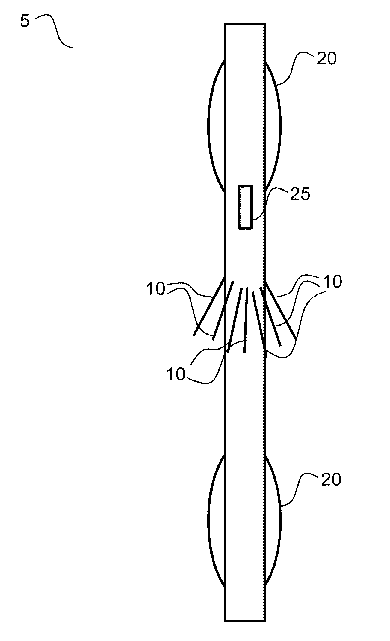
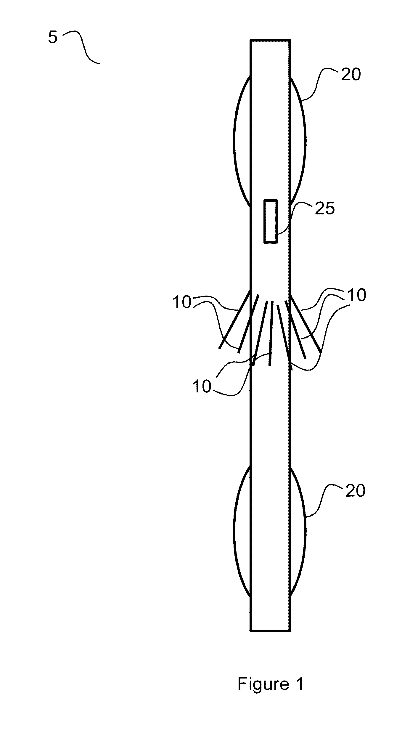
[0112]FIG. 1 shows a multi-fingered calliper tool 5. Such calliper tools 5 typically comprise a set of 24-80 callipers 10, that measure pipe radius to high precision, e.g. <0.25 mm (<0.01″).

[0113]There are a variety of suitable calliper tools 5 available. In one example of a suitable calliper tool 5, the callipers 10 are each pivotally mounted in a tool body 15 and biased radially outwardly using suitable biasing means (not shown). Respective rotation sensors (not shown) can then be used to measure the angle of the calliper. In this way, the measured angle of the calliper along with the known length of each calliper 10 and the fixed, known distance between the pivot of the calliper 10 and the centre of the tool body 15 can be used to determine a corresponding radius of a pipe, conduit, wellbore or other passage or hollow body in which the calliper tool 5 is inserted.

[0114]Two sets of mechanical centralisers 20 are provided on either side of the callipers 10. For example, the central...


PUM


Abstract

A method and associated system for determining geometry of a deformed pipe or conduit or wellbore, the method comprising: collecting, determining and/or receiving measurement data indicative of a plurality of radii of the pipe or conduit using equipment centred in the pipe at two or more points a known distance from the measurement point but not at the measurement point itself; selecting a deformation type and/or deformation model; processing the measurement data to determine one or more geometrical properties of the pipe or conduit, the geometrical properties being indicative of, or associated with, one or more deformations, shapes or profiles of at least part of the pipe or conduit; and guiding and/or constraining at least a part of the processing of the measurement data using the selected deformation type or model and/or fitting the selected deformation model to the measurement data.

Description

CROSS REFERENCE TO RELATED APPLICATIONS[0001]This application claims priority to United Kingdom Application No. 1406131.1, filed Apr. 4, 2014; the contents of which as are hereby incorporated by reference in their entirety.BACKGROUND[0002]1. Field of the Invention[0003]The present invention relates to a system and method for determining the geometry of deformed pipes. Particularly but not exclusively, the system and method determine geometrical properties of deformed parts of the pipe, for example, from multi-finger calliper data.[0004]2. Description of Related Art[0005]Tubulars and boreholes used in a variety of fields such as oil and gas production are often subject to deformations due to, for example, subsidence, mechanical damage, tectonic movement, mishandling, impact from other bodies or from other environmental pressures. Such deformations can impact on operations and safety involving the pipe or borehole, such as conveying tools, sensor or other devices through the pipe or i...

Claims


Application Information

Patent Timeline
IPC IPC(8): G01B3/24E21B47/02G01B3/56E21B47/08
CPCG01B3/24G01B3/56E21B47/02E21B47/08G01B5/12G01B5/207G01B5/252E21B47/00E21B49/00F16L55/00F16L55/26G01B5/00G01B5/0002G01B5/02G01B5/08G01B5/20G01B5/213G01B5/28G01B5/30G01M3/246G06Q50/02G09B23/40F16L2101/30G01M3/36G06T17/00E21B47/024E21B47/09
Inventor HELMORE, STEVE
Owner E V OFFSHORE
Why Eureka
Try Eureka