Beam shaping for reconfigurable holographic antennas

Active Publication Date: 2015-10-08
KYMETA
View PDF2 Cites 111 Cited by
  • Summary
  • Abstract
  • Description
  • Claims
  • Application Information

AI Technical Summary

Benefits of technology

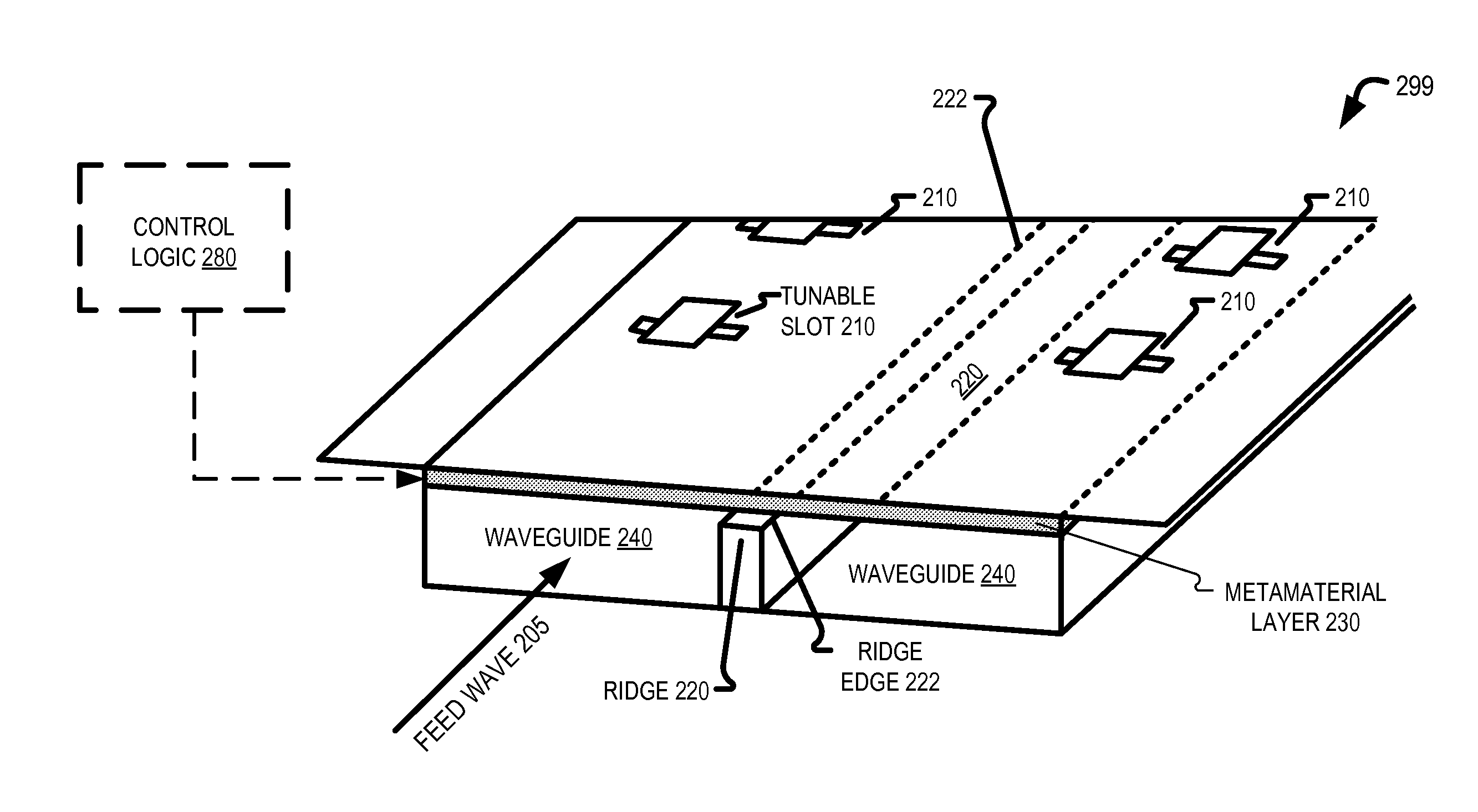
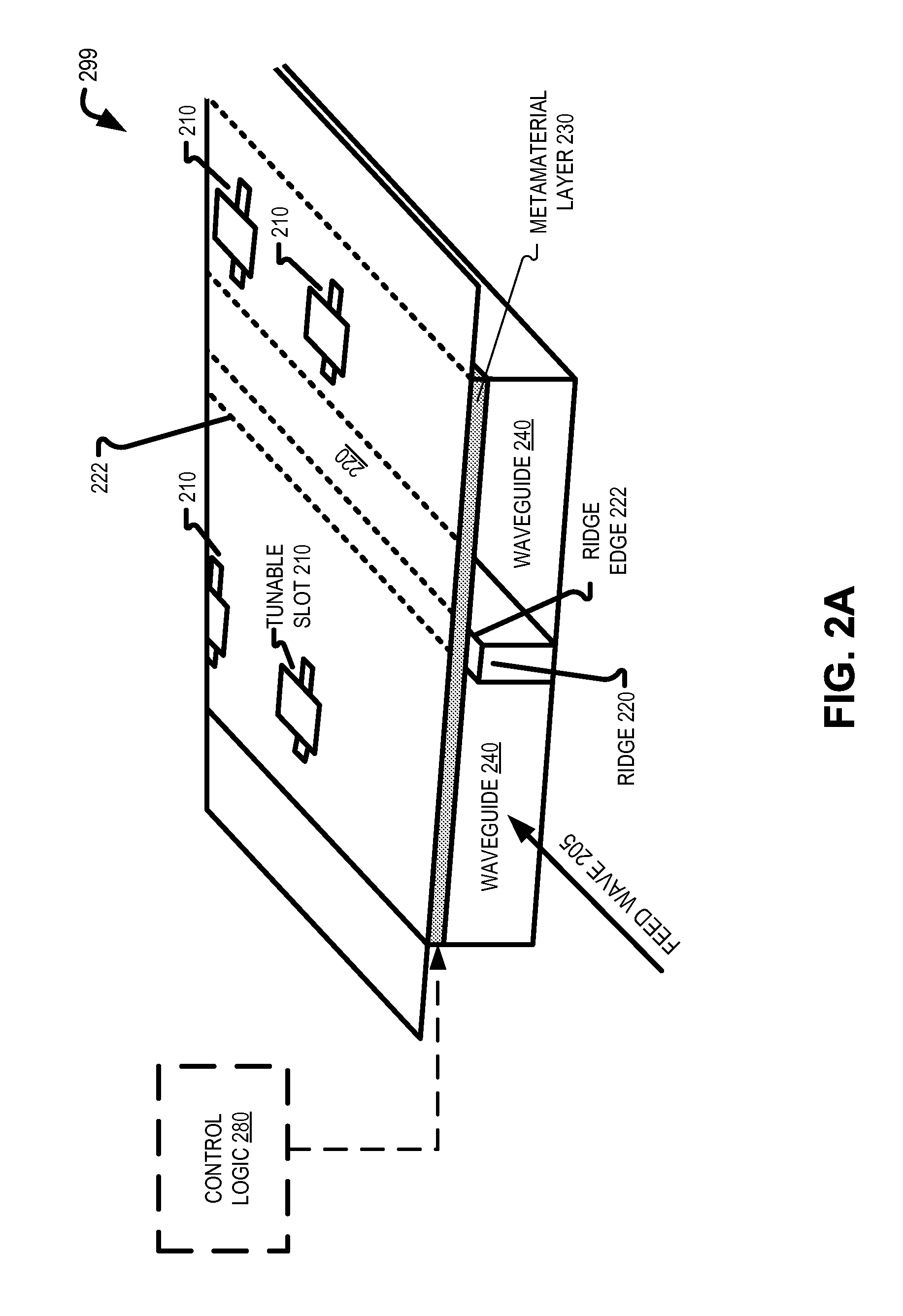
[0006]A reconfigurable holographic antenna and a method of shaping an antenna beam pattern in the reconfigurable holographic antenna are disclosed. In one embodiment, a method of shaping an antenna beam pattern in a reconfigurable holographic antenna includes driving a baseline holographic pattern onto a reconfigurable layer of the reconfigurable holographic antenna while a feed wave excites the reconfigurable layer. The method also includes receiv

Problems solved by technology

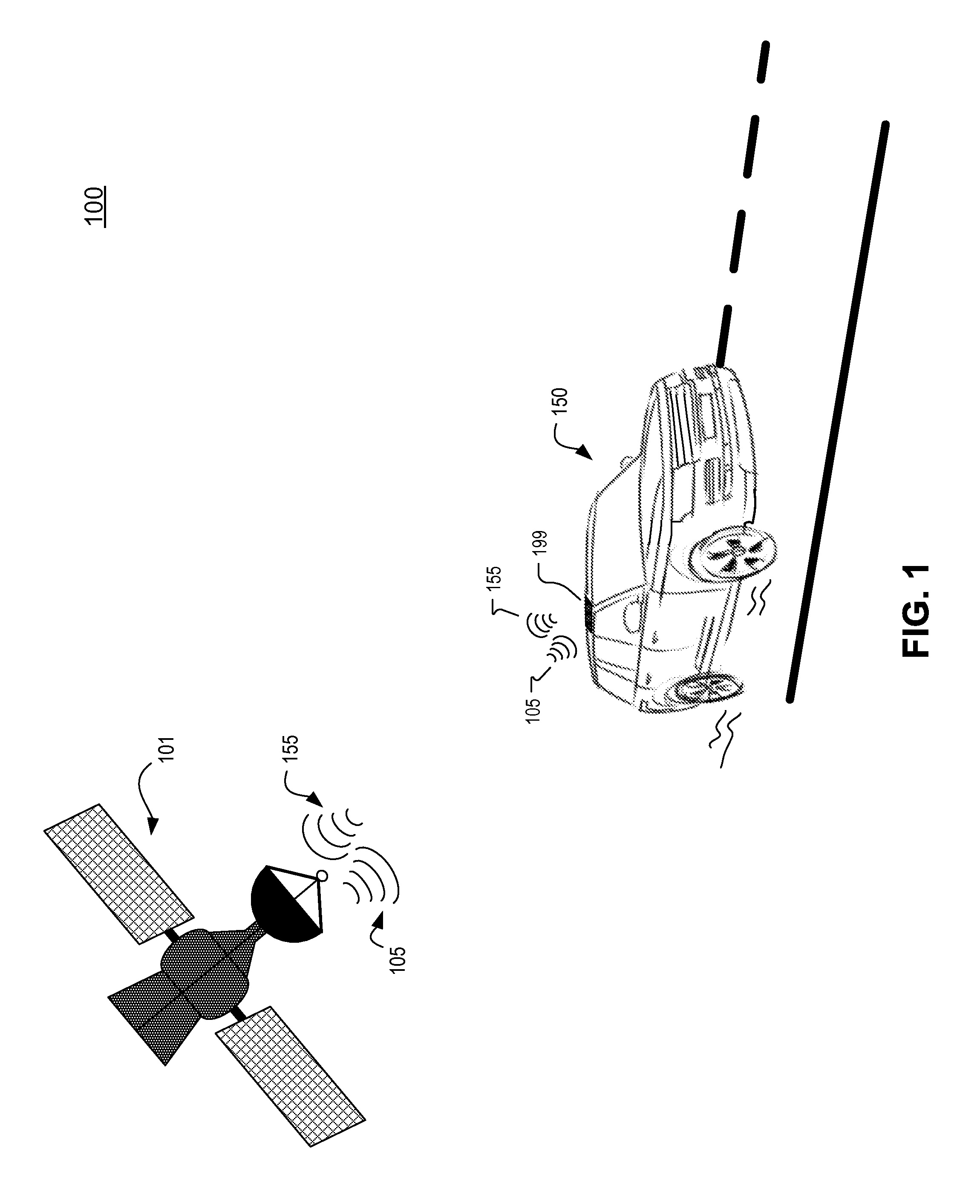
Transmitters and receivers of wireless data platforms present increased challenges when the transmitter and/or the receiver are moving.
However,

Method used


Image

  • Beam shaping for reconfigurable holographic antennas
  • Beam shaping for reconfigurable holographic antennas
  • Beam shaping for reconfigurable holographic antennas

Examples


Example

[0022]Embodiments of a reconfigurable holographic antenna, a communication system that includes a reconfigurable holographic antenna, and a method of shaping an antenna beam pattern of the reconfigurable holographic antenna are described herein. In the following description, numerous specific details are set forth to provide a thorough understanding of the embodiments. One skilled in the relevant art will recognize, however, that the techniques described herein can be practiced without one or more of the specific details, or with other methods, components, materials, etc. In other instances, well-known structures, materials, or operations are not shown or described in detail to avoid obscuring certain aspects.

[0023]Reference throughout this specification to “one embodiment” or “an embodiment” means that a particular feature, structure, or characteristic described in connection with the embodiment is included in at least one embodiment of the present invention. Thus, the appearances ...


PUM


Abstract

A reconfigurable holographic antenna and a method of shaping an antenna beam pattern of a reconfigurable holographic antenna is disclosed. A baseline holographic pattern is driven onto a reconfigurable layer of the reconfigurable holographic antenna while a feed wave excites the reconfigurable layer. An antenna pattern metric representative of a baseline antenna pattern is received. The baseline antenna pattern is generated by the reconfigurable holographic antenna while the baseline holographic pattern is driven onto the reconfigurable layer. A modified holographic pattern is generated in response to the antenna pattern metric. The modified holographic pattern is driven onto the reconfigurable layer of the reconfigurable holographic antenna to generate an improved antenna pattern.

Description

RELATED APPLICATIONS[0001]This application is a non-provisional application that claims priority to U.S. Provisional Application No. 61 / 976,292 entitled “Sidelobe Cancelation for Holographic Metamaterial Antenna,” filed Apr. 7, 2014. Provisional Application No. 61 / 976,292 is hereby incorporated by reference.TECHNICAL FIELD[0002]This disclosure relates generally to antennas, and in particular to reconfigurable holographic antennas.BACKGROUND INFORMATION[0003]Consumer and commercial demand for connectivity to data and media is increasing. Improving connectivity can be accomplished by decreasing form factor, increasing performance, and / or expanding the use cases of communication platforms. Transmitters and receivers of wireless data platforms present increased challenges when the transmitter and / or the receiver are moving.[0004]Satellite communication is one context where at least one of the transmitter and receiver may be moving. For example, satellite communication delivery to a resi...

Claims


Application Information

Patent Timeline
IPC IPC(8): H01Q3/26H01Q13/00H01Q15/00H01Q19/06
CPCH01Q3/26H01Q15/0086H01Q13/00H01Q19/067H01Q1/3275H01Q3/24H01Q21/005H01Q21/065H01Q13/10
Inventor JOHNSON, MIKALA C.ROTHAAR, BRUCE
Owner KYMETA
Why Eureka
Try Eureka