Self-adjusting crimping tool

Active Publication Date: 2015-10-08
WEIDMULLER INTERFACE GMBH & CO KG
View PDF0 Cites 2 Cited by
  • Summary
  • Abstract
  • Description
  • Claims
  • Application Information

AI Technical Summary

Benefits of technology

The patent is about a tool used for crimping electrical connector parts. The tool has a spring assembly with individual or groups of spring washers that can be adjusted in a simple way to compensate for different cross sectional shapes of the parts being crimped. The spring assembly can be placed on a base plate or in a lever of the tool, and can be connected to the crimping die using a tie rod. The use of the spring assembly allows the tool to better adapt to different cross sectional shapes, resulting in better crimping outcomes.

Problems solved by technology

In fact, the force-path-compensation device thus implemented permits processing of wire end ferrules with varied diameter; however, the type of spring design permits no optimal adaptation of spring force to the cross section to be processed.

Method used


Image

  • Self-adjusting crimping tool
  • Self-adjusting crimping tool
  • Self-adjusting crimping tool

Examples


Embodiment Construction

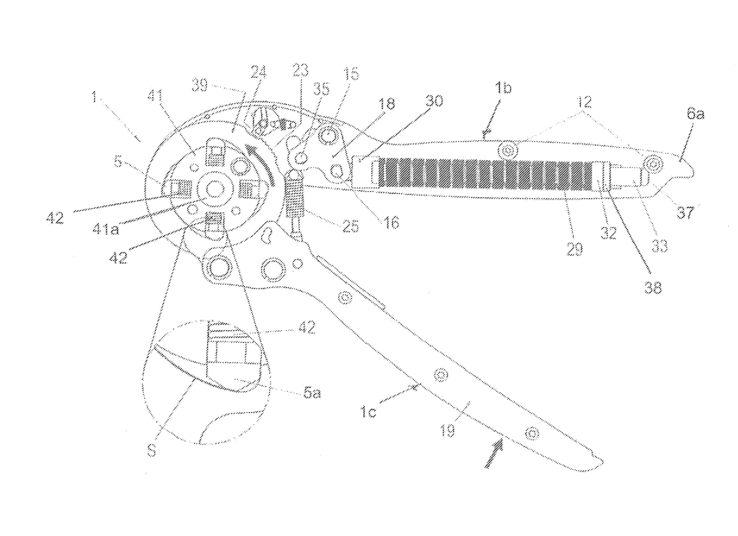
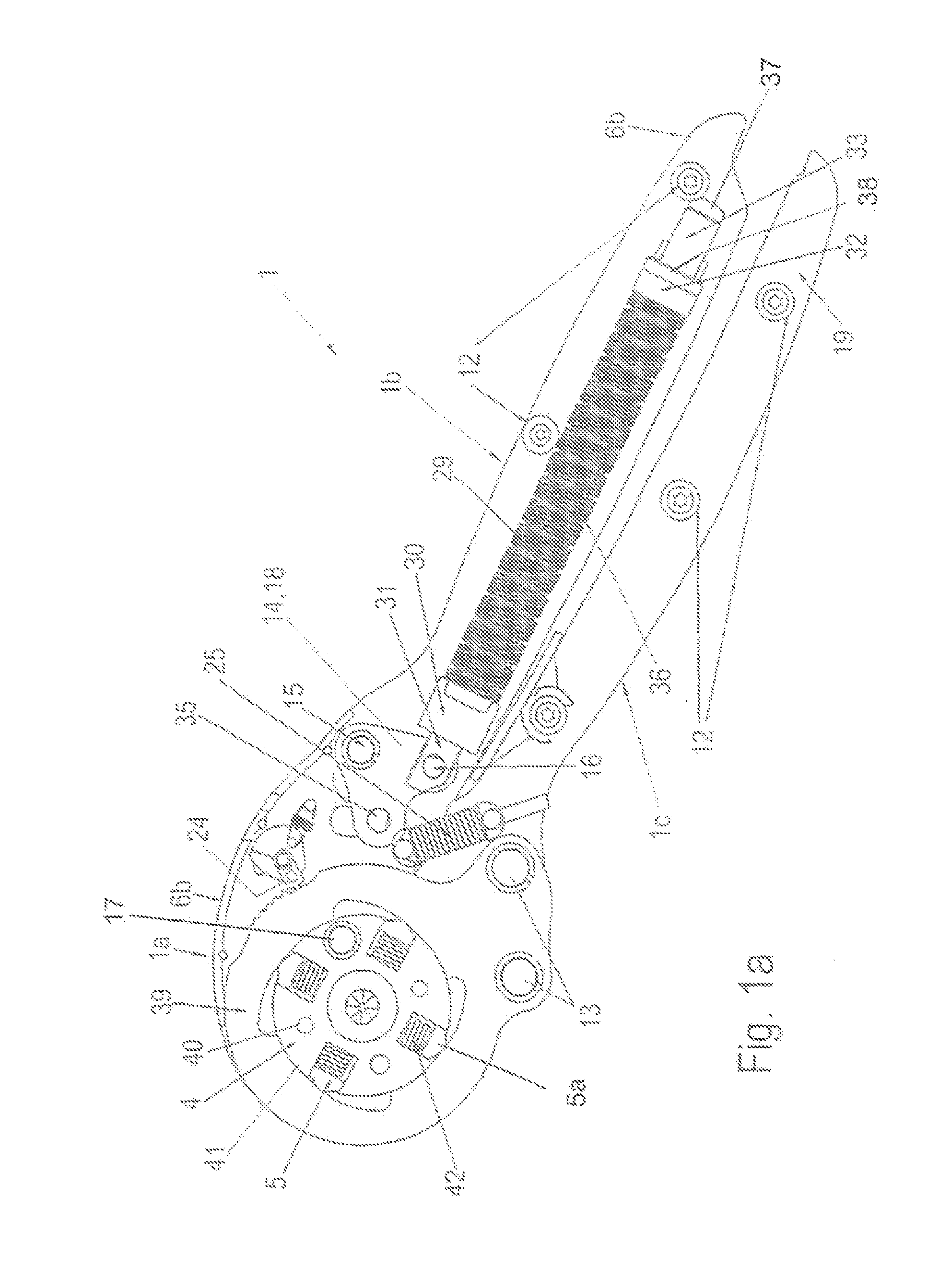
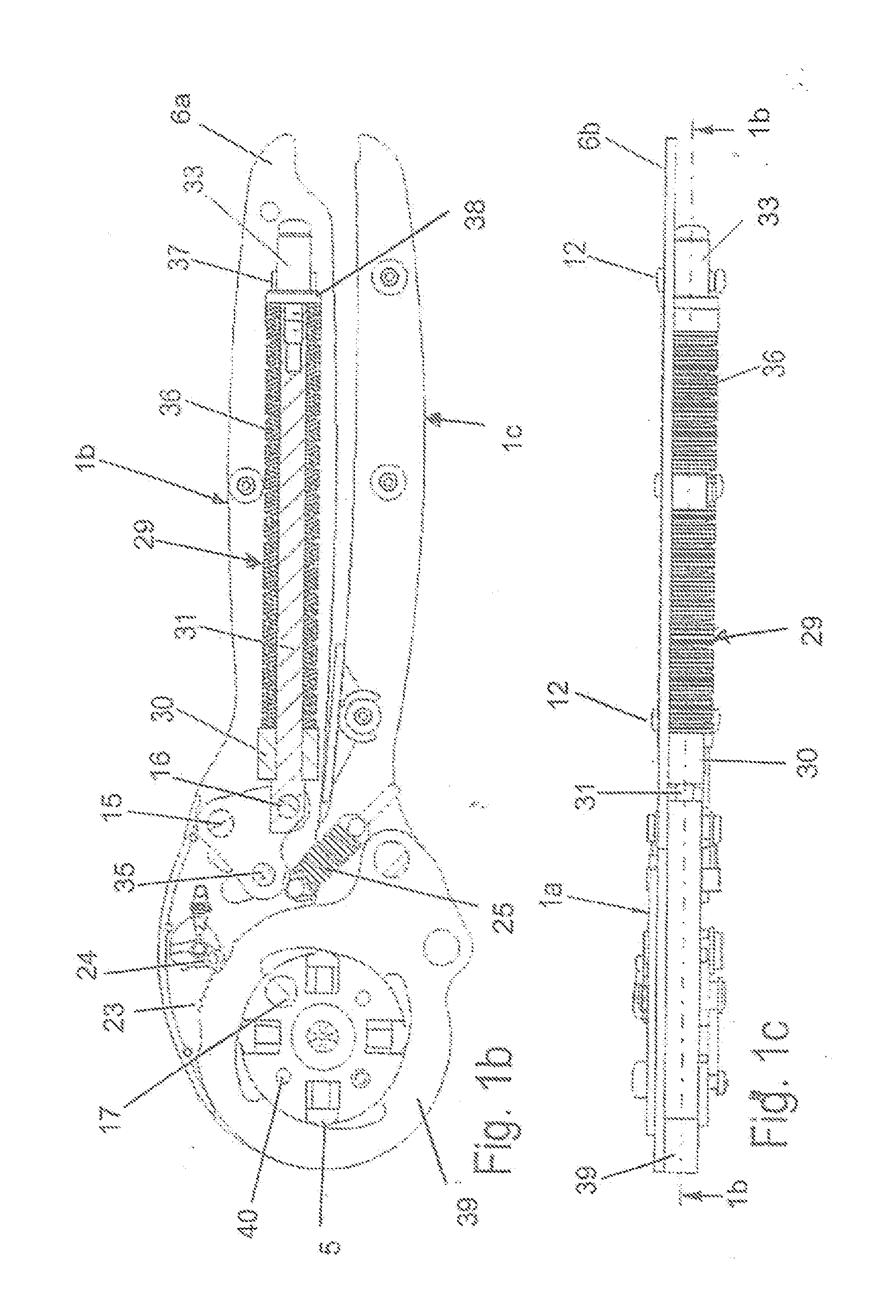
[0031]Briefly, with reference first more particularly to FIG. 1a, the crimping tool 1 of the present invention includes a tool head portion 1a that is integral with a fixed lever 1b, and is pivotally connected with a pivotal lever 1c. The fixed lever and the integral tool head portion include a pair of parallel spaced side plates 6a, 6b (FIG. 8b) that are fastened together on opposite sides of tubular spacer sleeves by bolts or rivets 12. Similarly, the pivotal lever 1c includes similar parallel spaced side plates that are bolted together by bolts or rivets 12 on opposite sides of tubular spacer sleeves.

[0032]Arranged between the tool head portions of the side plates 6a, 6b are crimping die means 4 including an annular crimping element holder 41 having central annular hub portions 41a. These hub portions extend axially outwardly from opposite sides of the crimping element holder into corresponding openings contained in the head portions of the side plates 6a and 6b, thereby permitti...


PUM

PropertyMeasurementUnit
Resilienceaaaaaaaaaa

Abstract

A self-adjusting pliers-type crimping tool includes a crimping arrangement having movable and fixed levers that are pivotally displaced from an open condition toward a fully closed condition, thereby to generate a first crimping force for crimping an electrical contact upon a bare conductor. When the levers are at an intermediate position, a predetermined compensating energy from a caged spring assembly is released and is applied to the crimping arrangement to complete the crimping process. The spring assembly may comprise a stack of spring washers, a helical spring arrangement, or a stack of resilient elastomeric blocks.

Description

BACKGROUND OF THE INVENTION[0001]1. Field of the Invention[0002]A self-adjusting pliers-type crimping tool includes a crimping arrangement having movable and fixed levers that are pivotally displaced from an open condition toward a fully closed condition, thereby to generate a first crimping force for crimping an electrical contact upon a bare conductor. When the levers are at an intermediate position, a predetermined compensating energy from a caged spring assembly is released and is applied to the crimping arrangement to complete the crimping process.[0003]2. Description of Related Art[0004]German Patent No. DE 100 60 165 A1 discloses a crimping tool which is adjusted manually to each individual cross section. It is desirable to produce a crimping tool for pressing of wire end ferrules and / or twisted contacts on the ends of cables, which, with a simple mechanical design and simple manipulation, permits crimping of ends of cables over a relatively wide range of cross section. Prefe...

Claims


Application Information

Patent Timeline
IPC IPC(8): H01R43/042
CPCH01R43/0424Y10T29/53226H01R43/0488H01R43/042
Inventor DIERKS, CHRISTOPHHANNING, GUENTHERHETLAND, DETLEVKELLER, DAVID
Owner WEIDMULLER INTERFACE GMBH & CO KG
Why Eureka
Try Eureka