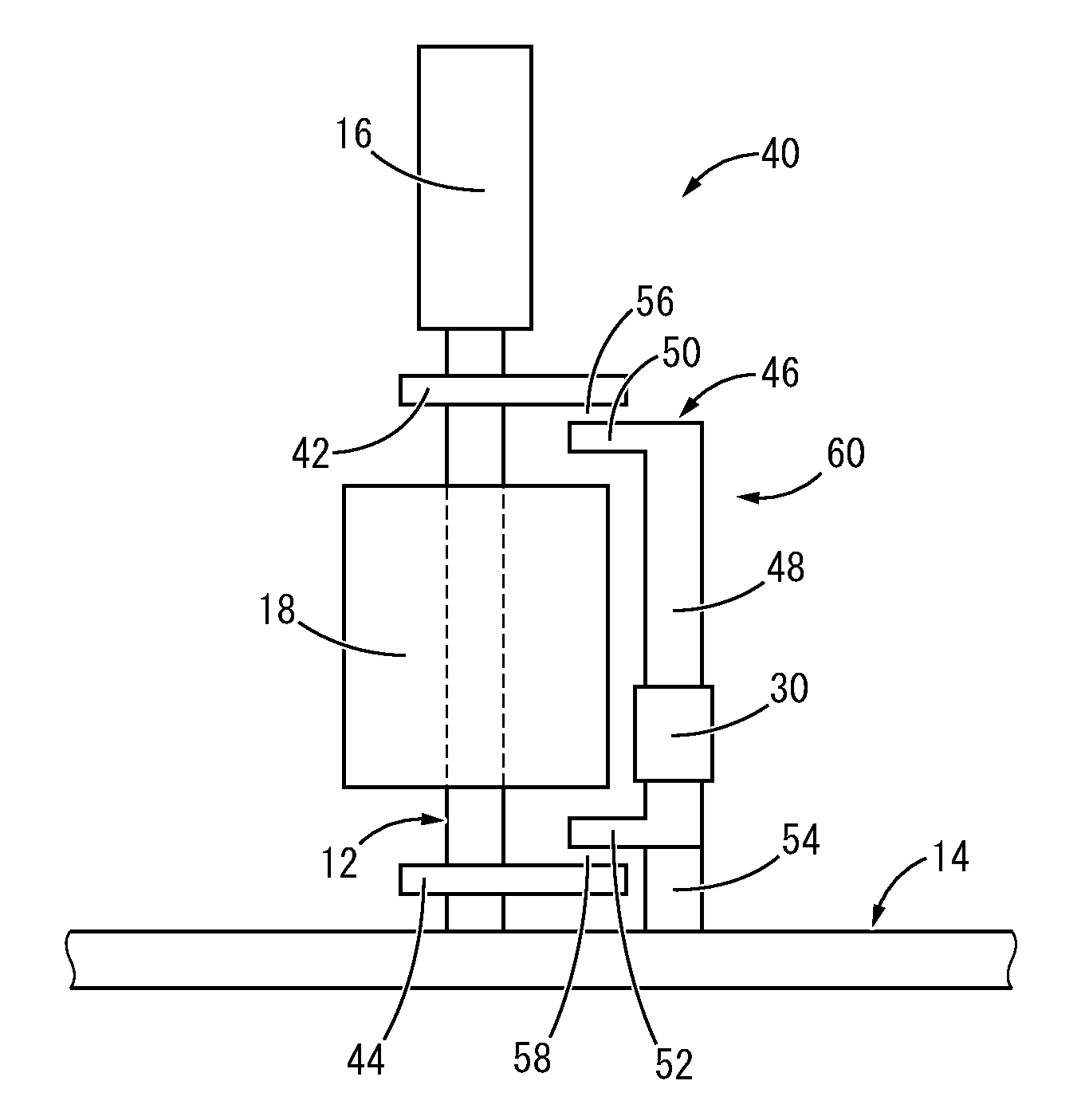
Magnetostrictive vibration power generation device
a power generation device and magnetic field technology, applied in the direction of magnetostrictive devices, piezoelectric/electrostrictive/magnetostrictive devices, piezoelectric/electrostriction/magnetostriction machines, etc., can solve problems such as damage risk, and achieve the effect of large power generation volume and efficient application of large vibration deformation
- Summary
- Abstract
- Description
- Claims
- Application Information
AI Technical Summary
Benefits of technology
Problems solved by technology
Method used
Image
Examples
first embodiment
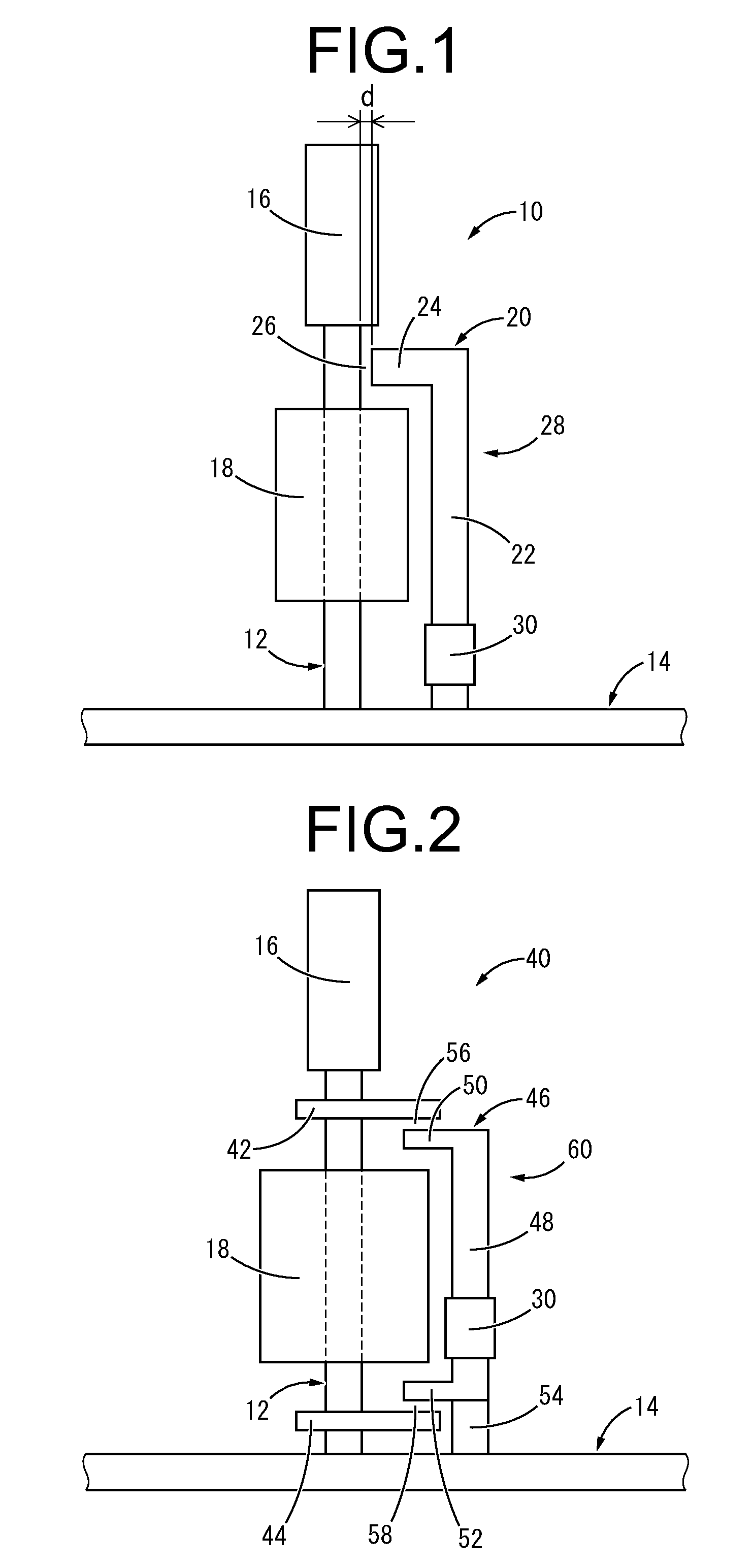
[0049]FIG. 1 shows a magnetostrictive vibration power generation device 10 (hereafter called “vibration power generation device 10”) as the present invention. The vibration power generation device 10 is equipped with a magnetostrictive element 12 as a power generating element that converts vibration energy to electric energy. With the description hereafter, the vertical direction means the vertical direction in FIG. 1 as a rule.
[0050]In more detail, the magnetostrictive element 12 is formed of a magnetostrictive material and has a longitudinal shape extending in a straight line in the vertical direction, and with this embodiment, has a solid rod shape extending at the small diameter circular cross section. The forming material of the magnetostrictive element 12 is not particularly restricted as long as it is an item for which sufficient change of magnetic permeability can occur in relation to deformation, but an iron type magnetostrictive material which has excellent strength is pre...
third embodiment
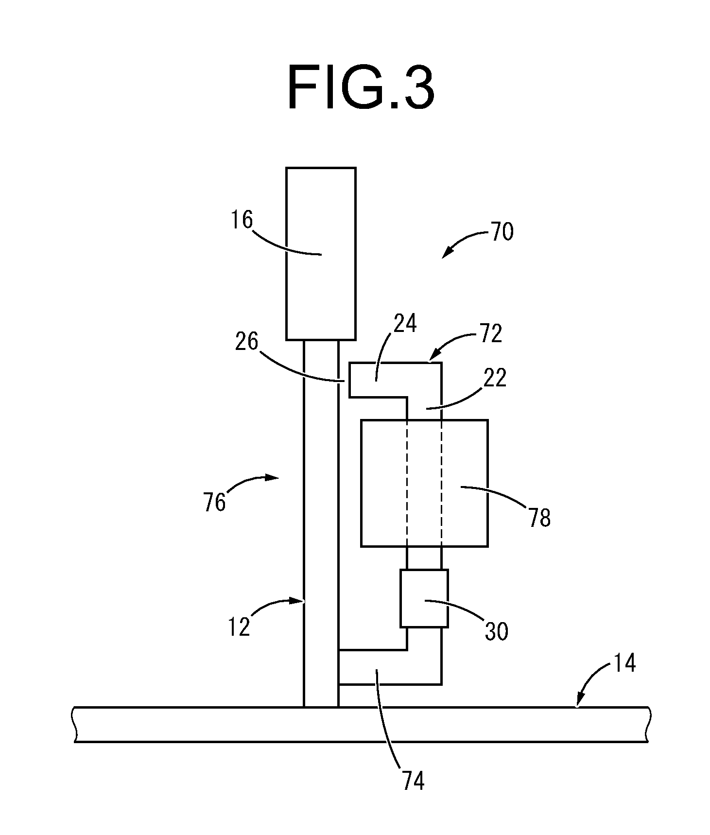
[0069]FIG. 3 shows a magnetostrictive vibration power generation device 70 as the present invention. The vibration power generation device 70 is constituted including a yoke member 72. The yoke member 72 is equipped with a rod shaped main unit part 22 arranged with a gap at the side of the magnetostrictive element 12 and extending roughly parallel, a projecting part 24 projecting toward the magnetostrictive element 12 from the top end of the main unit part 22, and a coupling support part 74 that couples the bottom end of the main unit part 22 to the magnetostrictive element 12. Also, a closed magnetic path 76 is formed by the magnetostrictive element 12 and the yoke member 72.
[0070]Furthermore, the permanent magnet 30 is fixed to the main unit part 22 of the yoke member 72 constituting the closed magnetic path 76, and a coil 78 is wound, the magnetic flux of the permanent magnet 30 is applied as a bias magnetic field to the closed magnetic path 76, and the bias magnetic field pierce...
fourth embodiment
[0073]FIG. 4 and FIG. 5 show a magnetostrictive vibration power generation device 80 as the present invention. With the vibration power generation device 80, a yoke member 82 is equipped with a main unit part 22 extending in parallel with the magnetostrictive element 12, and a projecting part 84 projecting toward the magnetostrictive element 12 from the top end of the main unit part 22.
[0074]As shown in FIG. 4 and FIG. 5, the projecting part 84 has a roughly rectangular plate shape that expands in the axis-perpendicular direction, and extends out past the magnetostrictive element 12, and also, has an insertion hole 86 formed piercing through vertically, and has the magnetostrictive element 12 inserted through the insertion hole 86. This insertion hole 86 has a circular cross section with a diameter larger than the diameter of the magnetostrictive element 12, and in a state with the magnetostrictive element 12 inserted through the insertion hole 86, a ring shaped gap 88 that is conti...
PUM
 Abstract
Description
Claims
Application Information
 - R&D
- Intellectual Property
- Life Sciences
- Materials
- Tech Scout
- Unparalleled Data Quality
- Higher Quality Content
- 60% Fewer Hallucinations
Browse by: Latest US Patents, China's latest patents, Technical Efficacy Thesaurus, Application Domain, Technology Topic, Popular Technical Reports.
© 2025 PatSnap. All rights reserved.Legal|Privacy policy|Modern Slavery Act Transparency Statement|Sitemap|About US| Contact US: help@patsnap.com


