
Device for molding and method for molding metal plate

a metal plate and device technology, applied in fuel cell details, collectors/separators, domestic applications, etc., can solve the problems of metal plate material warpage or undulation, easy to occur in metal plate material deformation, complex processing steps, etc., to prevent material from being broken, effective use of sidewall material, uniform thickness

Active Publication Date: 2015-10-15
TOYOTA BOSHOKU KK
View PDF2 Cites 12 Cited by
  • Summary
  • Abstract
  • Description
  • Claims
  • Application Information

AI Technical Summary

Benefits of technology

The invention is about a method for making a protruding portion of a metal plate material. The method involves using two molding tools, the first tool to draw out the material and make the top of the protruding portion thinner, and the second tool to roll out the sidewall of the protruding portion. This process prevents the material from breaking and effectively uses the material of the sidewall. It also results in a protruding portion that has a uniform thickness and excellent strength distribution and stress distribution, improving its breaking strength.

Problems solved by technology

The following problems have resided in the conventional molding methods.
Therefore, deformations, such as warpage or undulation, easily occur in the metal plate material 52 that has been molded.
However, in this case, the processing step becomes complex.

Method used


Image

  • Device for molding and method for molding metal plate
  • Device for molding and method for molding metal plate
  • Device for molding and method for molding metal plate

Examples


first embodiment

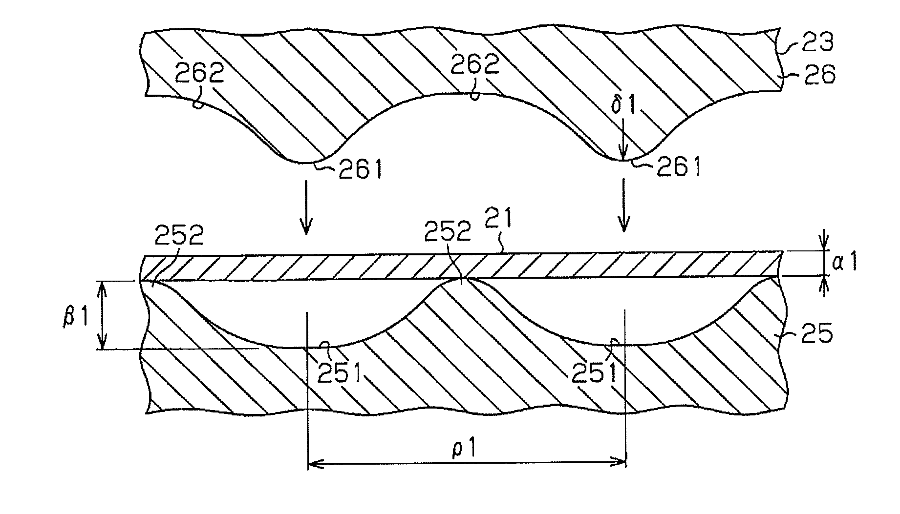
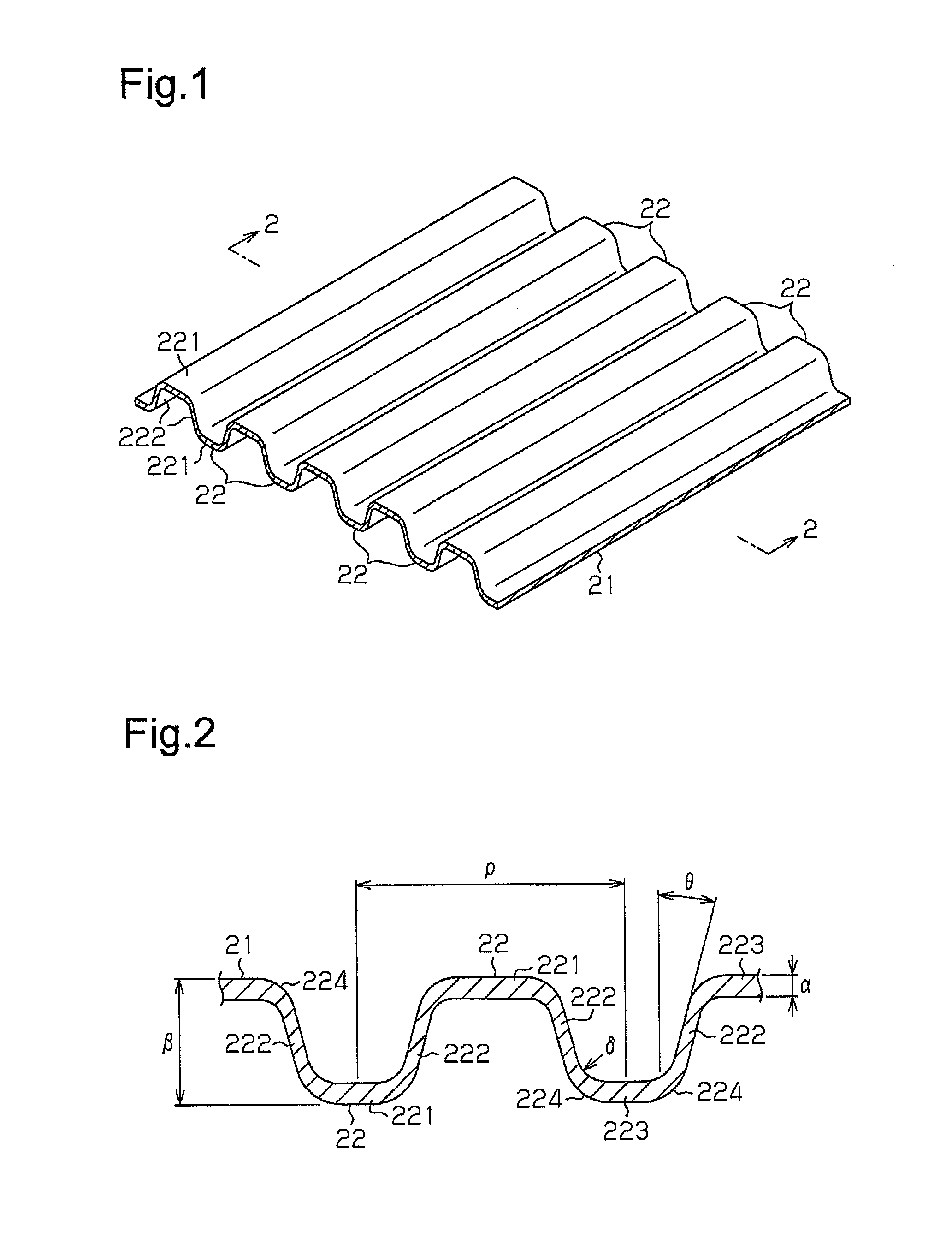
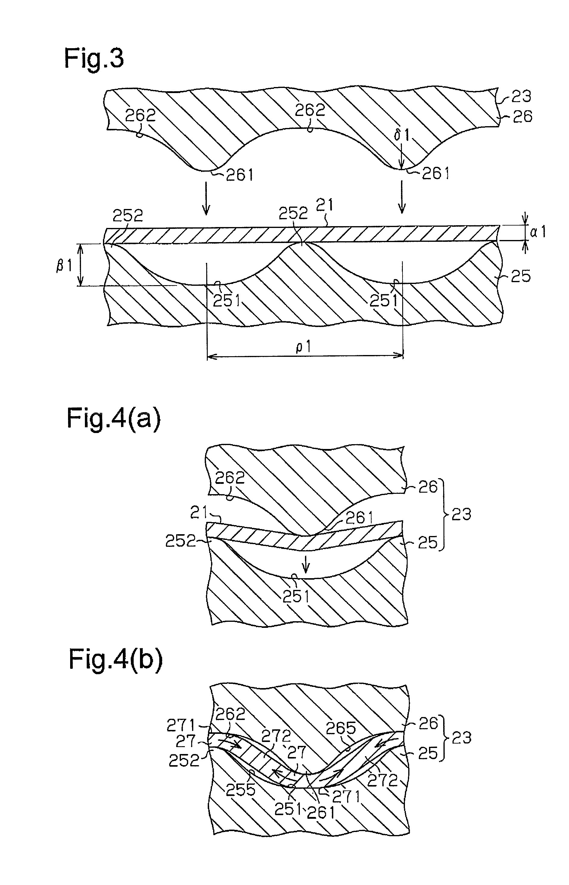
[0034]Referring to FIG. 1 to FIG. 11, a description will be hereinafter given of a first embodiment in which a method for molding a metal plate material according to the present invention is employed to manufacture fuel cell separators.

[0035]As shown in FIG. 1 and FIG. 2, a plurality of protruding portions 22 are formed on both sides of a metal plate material 21 that is made into a fuel cell separator. The protruding portions 22 are molded to be evenly spaced in a pleated shape. A material excellent in corrosion resistance, such as titanium, titanium alloys, or stainless steel, is used as the metal plate material 21. In this embodiment, titanium is used.

[0036]As shown in FIG. 3, the thickness al of the flat metal plate material 21 that has not yet been molded is uniform as a whole. The thickness al falls within the range of from 0.06 to 0.20 mm, and, in this embodiment, it is 0.10 mm. As shown in FIG. 2, the thickness a of the metal plate material 21 that has been molded is uniform ...

second embodiment

[0066]Next, a second embodiment of the present invention will be described with reference to FIG. 10 to FIG. 14. In the second embodiment, a detailed description of the same component as in the first embodiment is omitted.

[0067]As shown in FIG. 10, a plurality of protruding portions 22 are formed on both sides of the metal plate material 21 that is made into a fuel cell separator. The protruding portions 22 are formed in a dimpled shape and are evenly spaced out.

[0068]As shown in FIG. 11, each protruding portion 22 is composed of a top 221 and inclined sidewalls 222 continuous with the top 221. The cross section of the protruding portion 22 has a trapezoidal shape. The protruding portion 22 is molded substantially in the same way as in the first embodiment in order shown in FIG. 12 to FIG. 14. In other words, that is molded in order of a first step that uses the first molding tool 23, a second step that uses the second molding tool 24, and a third step that uses the third molding to...


PUM

PropertyMeasurementUnit
thicknessaaaaaaaaaa
thicknessaaaaaaaaaa
thicknessaaaaaaaaaa

Abstract

A protruding portion is formed in a metal plate material by use of a plurality of molding tools each of which has a die and a punch. In a first step, an initial protruding portion is formed in the metal plate material by use of a first molding tool. In this step, a top of the initial protruding portion is formed to be thinner than other parts. In a second step, a sidewall of the initial protruding portion is rolled out by use of a second molding tool, and the protruding portion is formed.

Description

TECHNICAL FIELD[0001]The present invention relates to a method for and a device for molding a metal plate material in which the metal plate material is molded to have a protruding portion by means of a molding tool having a die and a punch.BACKGROUND ART[0002]Conventionally, a fuel cell separator has been known in which flow passages through which a gas, such as hydrogen or oxygen, or cooling water flows are formed by forming a plurality of protruding portions in a metal plate material. For example, methods disclosed by Patent Document 1 and Patent Document 2 have been proposed as methods for molding this fuel cell separator.[0003]According to the molding method of Patent Document 1, as shown in FIG. 15(a), a small projection 421 is formed in a metal plate material 42 by means of a mold 411 and a mold 412 of a first molding tool 41. Thereafter, as shown in FIG. 15(b) and FIG. 15(c), the inside of the peripheral edge of the small projection 421 is pressed by a mold 431 and a mold 432...

Claims


Application Information

Patent Timeline
Patent Type & Authority Applications(United States)
IPC IPC(8): B21D13/02
CPCB21D13/02B21K23/00H01M8/0206Y02E60/50B21D11/085
Inventor HIRATA, KAZUYUKIWATANABE, TAKUMASAHARA, HIDEKAZU
Owner TOYOTA BOSHOKU KK
Learn More