
Device packaging method and device package using the same

Inactive Publication Date: 2015-10-15
KOREA ADVANCED INST OF SCI & TECH
View PDF12 Cites 0 Cited by
  • Summary
  • Abstract
  • Description
  • Claims
  • Application Information

AI Technical Summary

Benefits of technology

The present patent is related to a method and device package for packaging electronic devices. The technical effects of the patent include the formation of a package sacrificial layer by applying a first material on a device-formed substrate, the formation of a package cap by applying a second material on the package sacrificial layer, and the generation of gas molecules from the package sacrificial layer through external stimuli such as light or heat. The gas molecule can then be heated and form a cavity between the device and the package cap, with the degree of response of the package sacrificial layer to external stimuli controlled through heating. The package cap can then be developed, including patterning and the formation of a discharge hole for discharging the package sacrificial layer and gas. The device package formed in this way provides a cavity that protects the device from environmental factors and provides a more robust and reliable packaging solution.

Problems solved by technology

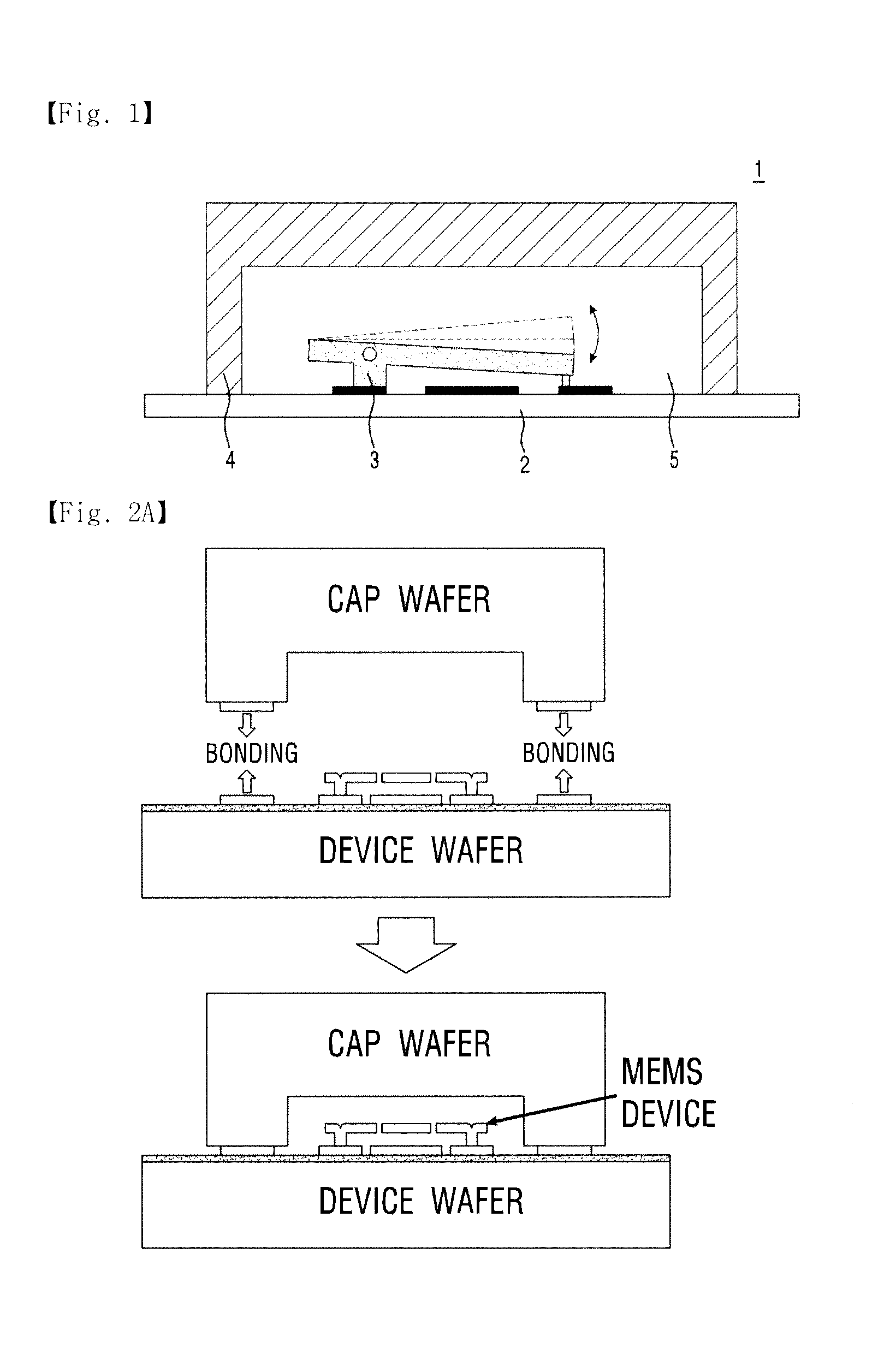
In the wafer bonding, since the temperature of the bonding is very high and a separate space for bonding is required at the border of the MEMS device, the packaging size is very large.
As a result, the completed MEMS device may be damaged during the packaging process.
Further, the wafer of the cap is additionally required, and thus, cost is increased.
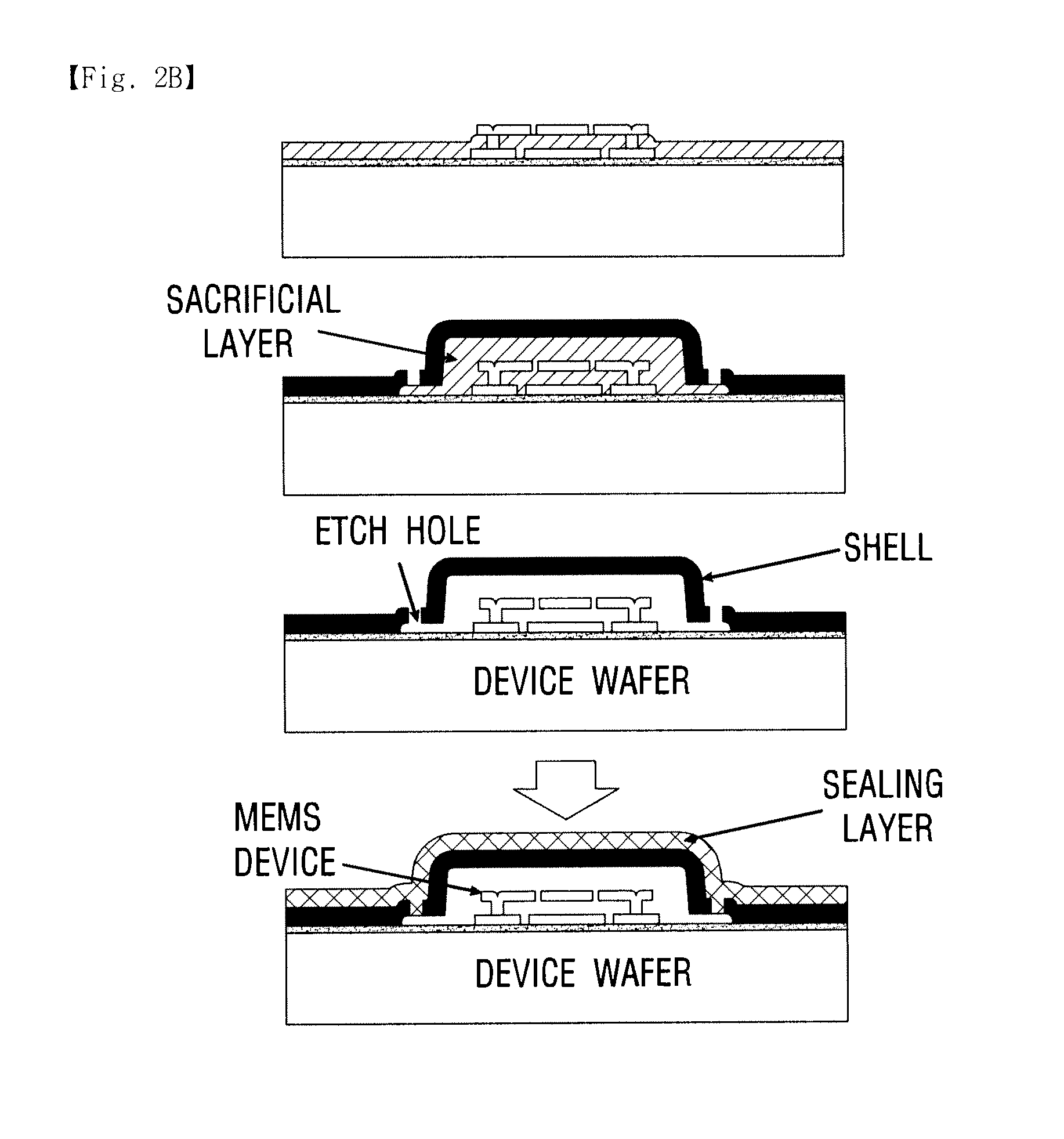
However, it takes much time to remove the sacrificial layer.
However, the sacrificial layer is deposited on the internal MEMS device or gas generated by the removal of the sacrificial layer is not easy to emit to the outside, so that the thin film is damaged.

Method used


Image

  • Device packaging method and device package using the same
  • Device packaging method and device package using the same
  • Device packaging method and device package using the same

Examples


Embodiment Construction

[0035]The following detailed description of the present invention shows a specified embodiment of the present invention and will be provided with reference to the accompanying drawings. The embodiment will be described in enough detail that those skilled in the art are able to embody the present invention. It should be understood that various embodiments of the present invention are different from each other and need not be mutually exclusive. For example, a specific shape, structure and properties, which are described in this disclosure, may be implemented in other embodiments without departing from the spirit and scope of the present invention with respect to one embodiment. Also, it should be noted that positions or placements of individual components within each disclosed embodiment may be changed without departing from the spirit and scope of the present invention. Therefore, the following detailed description is not intended to be limited. If adequately described, the scope of...


PUM

PropertyMeasurementUnit
Pressureaaaaaaaaaa

Abstract

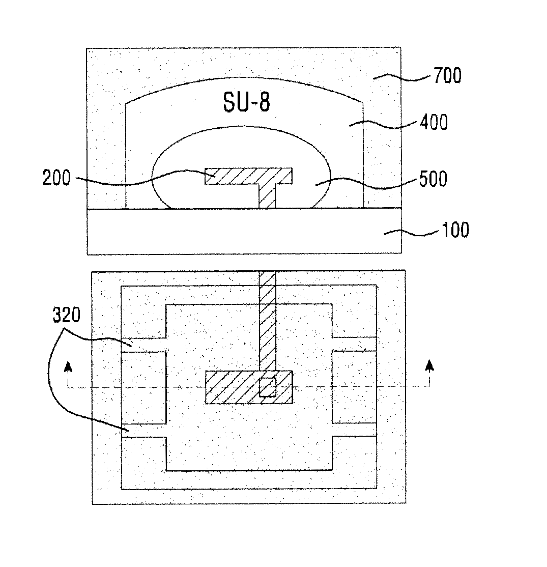
A device packaging method and a device package using the same may be provided. The device packaging method includes forming a package sacrificial layer by applying a first material on a substrate on which a device has been formed; forming a package cap by applying a second material on the package sacrificial layer; generating gas molecules from the package sacrificial layer by applying external stimuli such as light or heat to the package sacrificial layer; and heating the gas molecule and forming a cavity between the device and the package cap.

Description

CROSS REFERENCE TO RELATED APPLICATIONS[0001]This application claims priority to South Korean Application No. 10-2014-0044469 filed Apr. 14, 2014, the contents of which are herein incorporated by reference in its entirety.BACKGROUND[0002]1. Field[0003]The embodiment may relate to a device packaging method and a device package using the same.[0004]2. Description of Related Art[0005]Recently, products are now being actively developed by applying micro-electro mechanical system (MEMS) technology which is advantageous for micro-miniaturization and high-precision. Various technologies for forming a MEMS device package including a fixed part which is fixed by various methods and an actuator which moves with respect to the fixed part are applied to the MEMS technology.[0006]As examples of an apparatus including the MEMS device package, there are an accelerometer, a pressure sensor, a flow sensor, a transducer, micro-actuators, and the like. The apparatus including the MEMS device package i...

Claims


Application Information

Patent Timeline
IPC IPC(8): B81C1/00B81B7/00
CPCB81C1/0038B81B7/0077B81C1/00333B81C1/00293B81C2203/0136
Inventor YOON, JUN BOHAN, CHANG HOONYOON, YONG HOONLEE, JAE SHIN
Owner KOREA ADVANCED INST OF SCI & TECH
Learn More