Catalytic conversion method and device for single-riser petroleum hydrocarbon type raw material

A catalytic conversion method and riser technology, applied in the field of single riser petroleum hydrocarbon feedstock catalytic conversion method and device, can solve the problems of inability to adjust the ratio of catalyst to oil, less catalyst storage, and inability to adjust and change, so as to reduce dry gas Yield, improvement of catalytic conversion reaction, effect of control

Inactive Publication Date: 2011-05-11
QINGDAO JINGRUN PETROCHEM DESIGN INST CO LTD
View PDF3 Cites 2 Cited by
  • Summary
  • Abstract
  • Description
  • Claims
  • Application Information

AI Technical Summary

Problems solved by technology

[0003] The riser reactor has the advantages of reducing the back-mixing of the reactants and improving the selectivity of the target product, but there are also disadvantages: precisely because it is close to "plug flow" and the catalyst storage is small, there is a temperature effect (endothermic or exothermic ) during the reaction process, it will inevitably cause a large temperature difference, which will affect the control of the reaction temperature and increase the by-product
[0005] Obviously another shortcoming of the current technology is that the reaction is controlled by the riser outlet temperature, and the amount of catalyst participating in the reaction is determined by the riser outlet temperature, which cannot be adjusted, and the reaction agent-oil ratio cannot be adjusted either.
[0006] Another disadvantage of the current technology is that the catalyst storage in the riser and the catalyst-oil ratio in each reaction zone are basically the same and cannot be adjusted.

Method used


Image

  • Catalytic conversion method and device for single-riser petroleum hydrocarbon type raw material
  • Catalytic conversion method and device for single-riser petroleum hydrocarbon type raw material
  • Catalytic conversion method and device for single-riser petroleum hydrocarbon type raw material

Examples


Embodiment 1

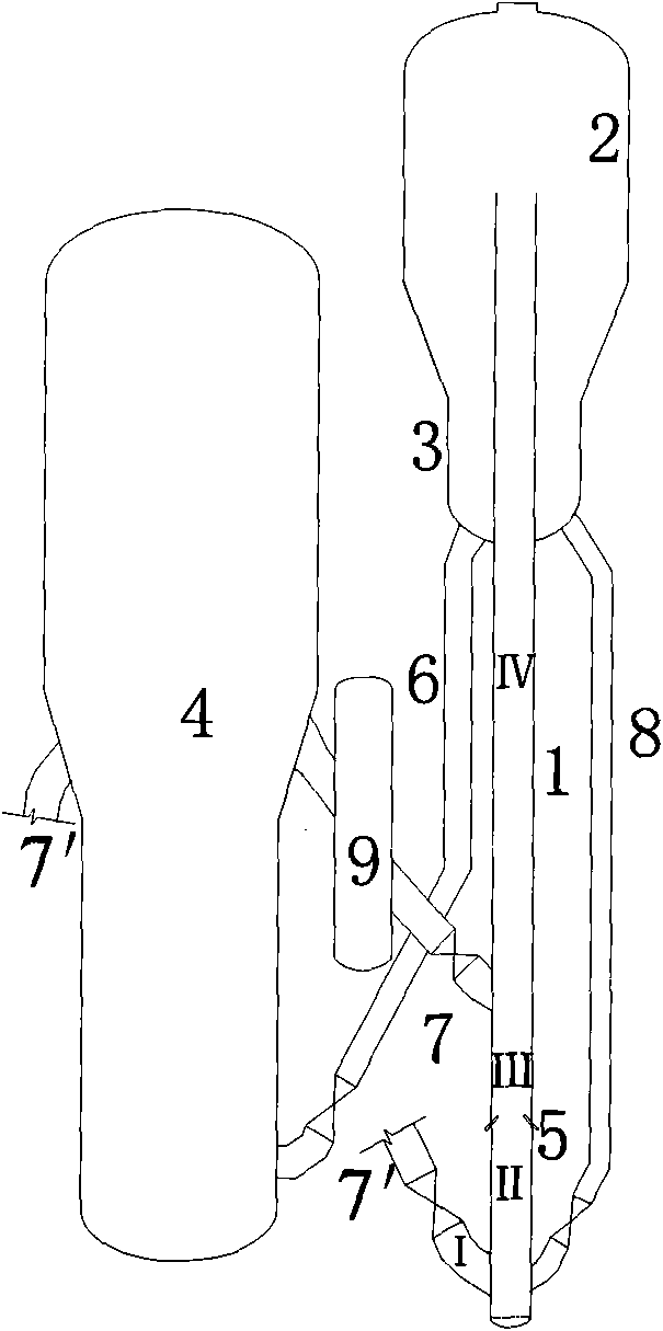
[0029] Example 1: see figure 1 . The ungenerated catalyst from the stripping section 3 returned through the catalyst return pipe 8 is mixed with a part of the hot regenerated catalyst entering from the regeneration standpipe 7' in the pre-lift section II at the bottom of the riser reactor 1, and then upwardly passes through the feed nozzle 5 The incoming atomized feedstock oil is contacted to participate in the catalytic reaction; the reaction mixture is upwardly contacted with the temperature-reduced regenerated catalyst formed by the regeneration standpipe 7 through the catalyst cooling device 9 and continues to react; the reactant flow is separated in the settler 2, and the The raw catalyst is stripped in the stripping section 3, part of it enters the pre-lift section II at the bottom of the reactor 1 through the return pipe 8, and the other part enters the regenerator 4 through the standpipe 6 for regeneration.

[0030] In this embodiment, the distribution of catalyst cir...

Embodiment 2

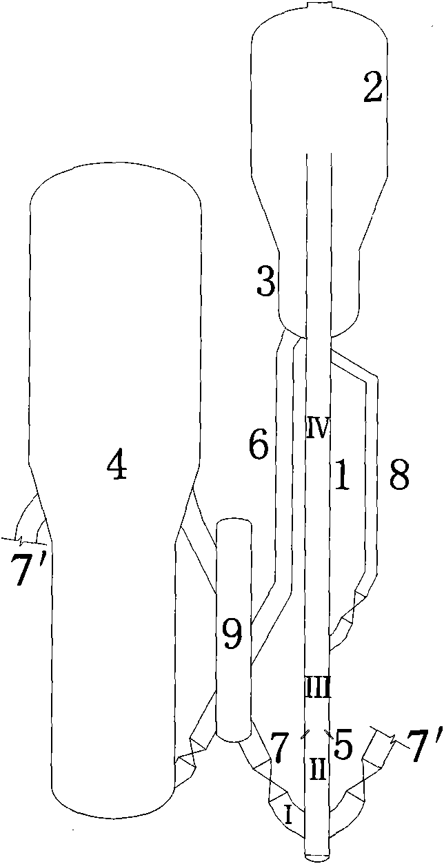
[0031] Example 2: see image 3. A part of the hot regenerated catalyst entering from the regeneration standpipe 7 passes through the catalyst cooler 9 to form a cooling regenerated catalyst, and after being mixed with another part of the hot regenerated catalyst entering from the regeneration standpipe 7′ in the pre-lift section II at the bottom of the riser reactor 1, Contact upward with the atomized raw material oil that enters through the feed nozzle 5 to participate in the catalytic reaction; the reaction mixture is upwardly contacted with the spent catalyst from the post-reaction section III that flows back through the catalyst return pipe 8 to continue the reaction; the reactant flows along the post-reaction section III Upward, a part of the catalyst to be produced is refluxed into the rear reaction section through the return pipe 8 to participate in the reaction, and the rest of the reaction mixture enters the settler 2 and the stripping section 3 upwards and is separat...

Embodiment 3

[0032] Embodiment 3: see Figure 4 . The cooled regenerated catalyst that enters from the regeneration riser 7 and is cooled by the catalyst cooler 9 enters the bottom of the riser reactor 1, and contacts upwardly with the atomized raw material oil that enters through the feed nozzle 5 to participate in the catalytic reaction; The raw catalyst from the stripping section 3 returned by the reflux pipe 8 contacts and continues to react; the reactant flow is separated in the settler 2, and the raw catalyst is stripped in the stripping section 3, and a part enters the riser reactor 1 through the reflux pipe 8 In the post-reaction section, the other part enters the regenerator 4 for regeneration through the standby riser 6.

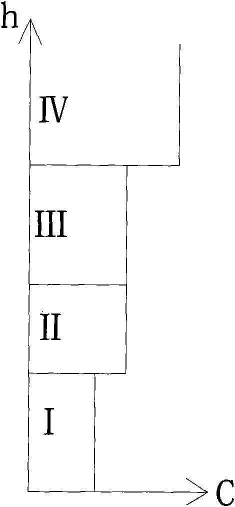
[0033] In this embodiment, the distribution of catalyst circulation from bottom to top along the riser reactor is as follows Figure 5 As shown, the cooling regenerated catalyst in the pre-lifting section II enters the oil agent contact section III upwards, a...


PUM


Abstract

The invention discloses a catalytic conversion method and a catalytic conversion device for a single-riser petroleum hydrocarbon type raw material. A catalyst which has a temperature lower than that of a regenerated catalyst is fed into a pre-rising section of a riser reactor and is conveyed into an oil-catalyst contact reaction section by pre-risen gas to be contacted with the raw material for catalytic conversion reaction; and a cooled regenerated catalyst or a reflowed spent catalyst is fed into the riser reactor from the space above a raw material nozzle to participate in the catalytic conversion reaction. By the method and the device, reaction dry gas can be reduced, product distribution can be improved, and the temperature or the catalyst-oil ratio of the riser oil-catalyst contact reaction section and a post-reaction section can be adjusted and controlled, so catalytic conversion has sufficient flexibility to adapt to change of quality of raw material oil or the requirement of a market on products.

Description

technical field [0001] The invention belongs to the technical field of petrochemical industry, and in particular relates to a catalytic conversion method and device for petroleum hydrocarbon raw materials with a single riser. Background technique [0002] Fluidized catalytic conversion is an important secondary processing technology in the petrochemical field. Most of the existing fluidized catalytic conversion devices for petroleum hydrocarbon raw materials use riser reactors. [0003] The riser reactor has the advantages of reducing the back-mixing of the reactants and improving the selectivity of the target product, but there are also disadvantages: precisely because it is close to "plug flow" and the catalyst storage is small, there is a temperature effect (endothermic or exothermic ) in the reaction process, it will inevitably cause a large temperature difference, which will affect the control of the reaction temperature and increase the by-products. [0004] In order ...

Claims


Application Information

Patent Timeline
Patent Type & Authority Applications(China)
IPC IPC(8): C10G11/14B01J8/16
Inventor 石宝珍
Owner QINGDAO JINGRUN PETROCHEM DESIGN INST CO LTD
Why Eureka
Try Eureka