Vehicle lighting device

a technology for vehicles and lighting devices, applied in fixed installation, light and heating equipment, transportation and packaging, etc., can solve problems such as optical loss, and achieve the effect of minimizing the optical loss of radiated ligh

Active Publication Date: 2015-10-15
ICHIKOH IND LTD
View PDF2 Cites 16 Cited by
  • Summary
  • Abstract
  • Description
  • Claims
  • Application Information

AI Technical Summary

Benefits of technology

[0008]An object of the present invention is to minimize an optical loss.
[0014]According to the above aspect of the vehicle lighting device of the invention, a plane is provided in at least one of a part of the exit surface for blocking a part of radiated light and a part of the reflection surface for blocking a part of radiated light. As a result, even when a light guide member of a first lamp unit is disposed in a position for blocking a part of radiated light from a second lamp unit, the radiated light from the second lamp unit passes through the plane of the reflection surface or the plane of the exit surface of the light guide member, and an optical loss of the radiated light can be minimized.

Problems solved by technology

In the above conventional vehicle lighting device, an optical loss may occur light when the light from the DRL unit passes through the translucent portion of the light guide lens.

Method used


Image

  • Vehicle lighting device
  • Vehicle lighting device
  • Vehicle lighting device

Examples


Embodiment Construction

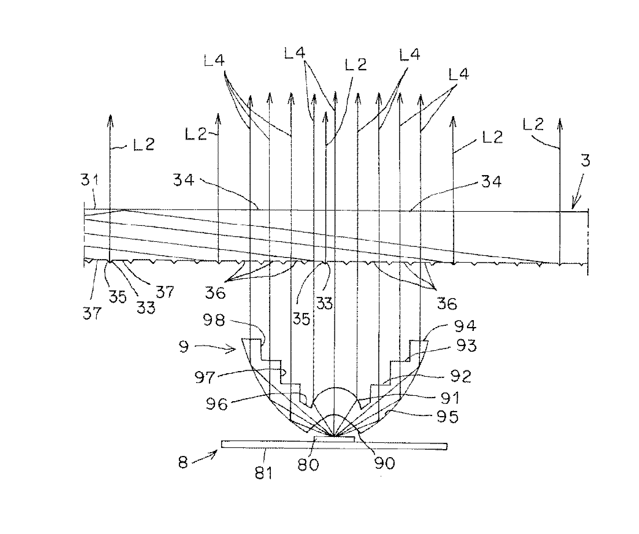
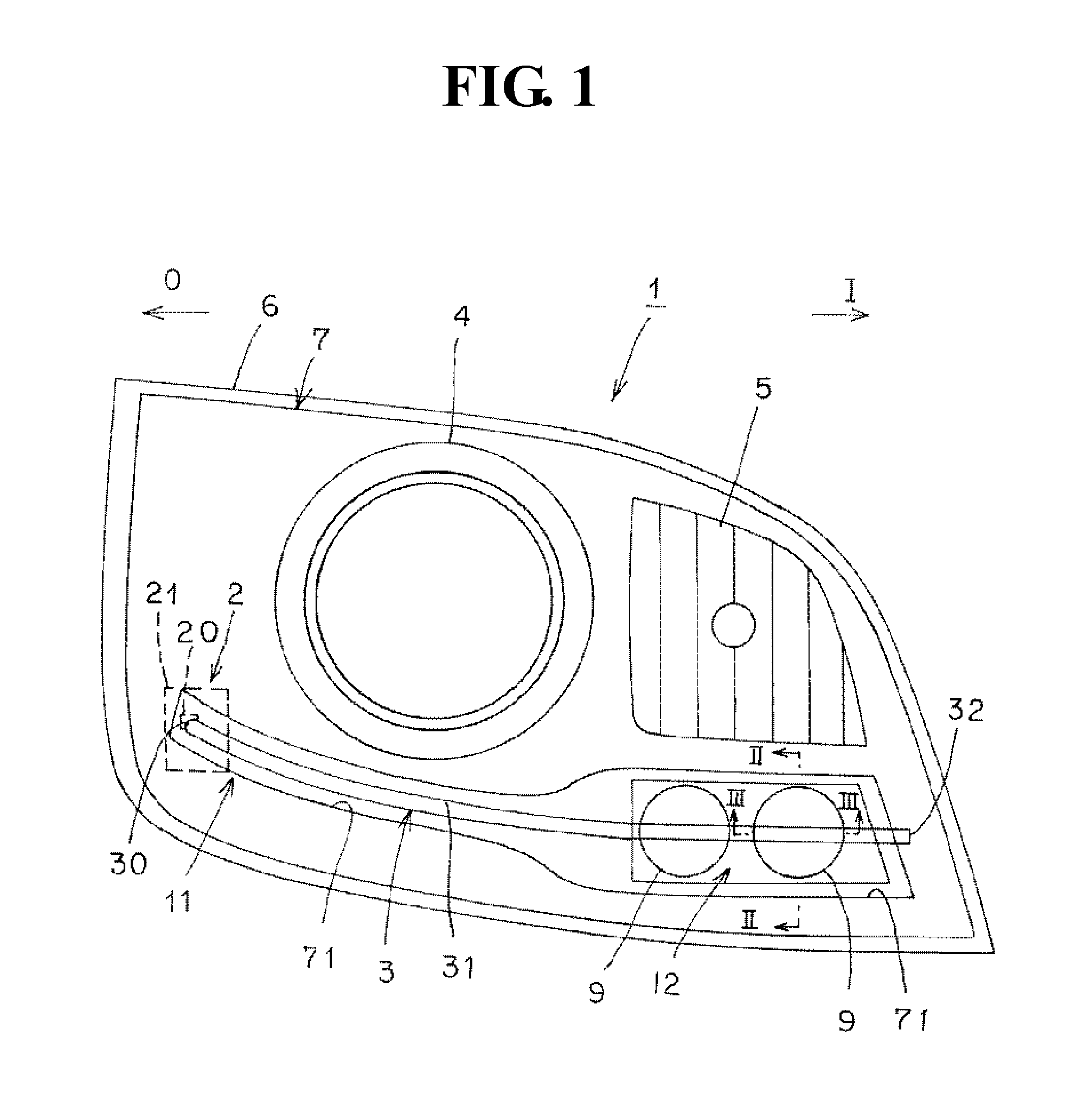
[0023]Hereinafter, an exemplary embodiment of a vehicle lighting device according to the present invention will be specifically described with reference to the accompanying drawings. The present invention is not limited to the embodiment. In the specification, front, back, top, bottom, left, right indicate front, back, top, bottom, left, right when the vehicle lighting device according to the invention is equipped in a vehicle.

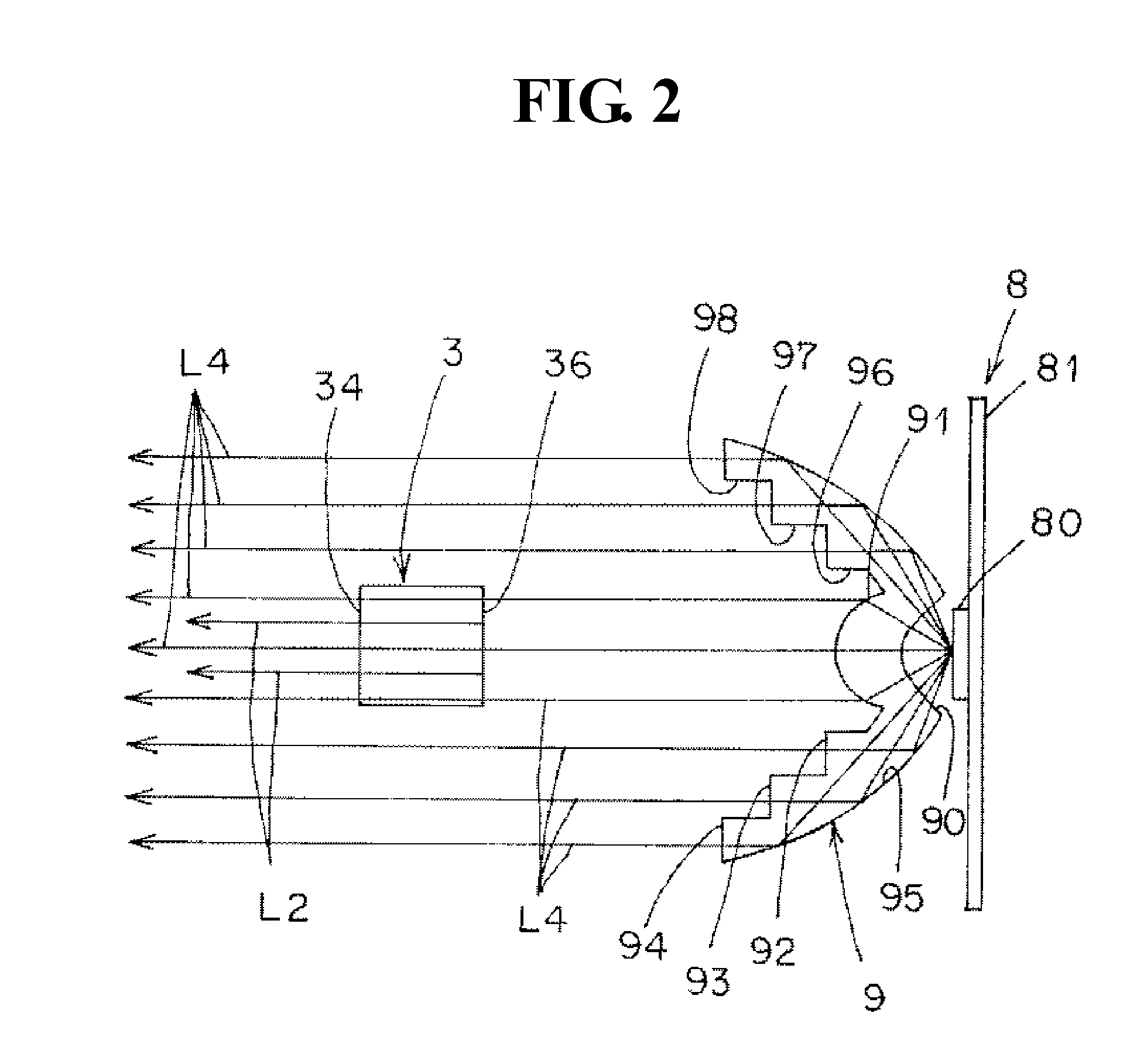
[0024]In FIG. 1, a symbol “I” indicates the inside of a vehicle, and a symbol “O” indicates the outside of a vehicle. In FIGS. 2 to 7, hatching of a light guide member is omitted. In FIGS. 2 and 3, hatching of a lens member is omitted. Light is indicated by a solid line arrow in the figures.

[0025](Description of Configuration of the Embodiment)

[0026]FIGS. 1 to 8 (A) show embodiments of the vehicle lighting device according to the invention. Hereinafter, the configuration of the vehicle lighting device according to the embodiments will be described. In FIG. 1, ...


PUM


Abstract

A present invention includes a lamp housing, a lamp lens, a first lamp unit, and a second lamp unit. The first lamp unit includes a semiconductor-type light source, and a light guide member. The light guide member has an exit surface, and a reflection surface. A plane exit surface is provided in a part of the exit surface for blocking a part of a radiated light L4 from the second lamp unit, and a plane incident surface is provided in a part of the reflection surface for blocking a part of the radiated light L4 from the second lamp unit. As a result, the present invention is able to minimize an optical loss of the radiated light L4, even when the light guide member is located at a position for blocking a part of the radiated light L4 from the second lamp unit.

Description

CROSS-REFERENCE TO RELATED APPLICATIONS[0001]This application claims priority of Japanese Patent Application No. 2014-080503 filed on Apr. 9, 2014. The contents of this application are incorporated herein by reference in their entirety.BACKGROUND OF THE INVENTION[0002]1. Field of the Invention[0003]The present invention relates to a vehicle lighting device comprising a light guide member.[0004]2. Description of the Related Art[0005]A vehicle lighting device comprising with a light guide member has been known before (e.g., JP-A-2014-29775). The conventional vehicle lighting device of the JP-A-2014-29775 will be explained below. The conventional vehicle lighting device comprises a headlamp unit (HL unit), and a daytime running lamp unit (DRL unit). The HL unit comprises a light source, and a light guide lens. The light guide lens has an incident surface, and a front reflection surface, a rear reflection surface, an exit surface, and a translucent portion.[0006]The conventional vehicle...

Claims


Application Information

Patent Timeline
Patent Type & Authority Applications(United States)
IPC IPC(8): F21S8/10
CPCF21S48/2237F21S48/24F21S48/1241B60Q1/0041B60Q1/0058B60Q2400/30F21S43/14F21S43/237F21S43/245F21S43/247F21S43/315F21S43/40
Inventor KOSHIRO, HIROSHI
Owner ICHIKOH IND LTD
Why Eureka
Try Eureka