Particle counter and classification system

a technology of particle counter and classification system, applied in the field of particle counter and magnetometer, can solve the problem that devices, however, do not classify magnetic particles according to morphology

Active Publication Date: 2015-10-15
SPECTRO SCI INC
View PDF0 Cites 17 Cited by
  • Summary
  • Abstract
  • Description
  • Claims
  • Application Information

AI Technical Summary

Benefits of technology

[0006]In one preferred embodiment, a dual-stage magnetometer is positioned behind an analysis cell associated with a particle imaging apparatus. In this way, particles from the same fluid can be imaged and counted. These same particles can then be characterized for their individual magnetic and conducting content using the dual-stage magnetometer. Finally, the dual-stage magnetometer can report the overall magnetic content of the fluid, which allows for particles which are too small to be imaged or characterized individually to be accounted for.

Problems solved by technology

Such devices, however, do not classify the magnetic particles according to morphology.
In addition, such devices typically either supply an overall ferromagnetic percent or information regarding individually observed particulate, but not both.

Method used


Image

  • Particle counter and classification system
  • Particle counter and classification system
  • Particle counter and classification system

Examples


Embodiment Construction

[0020]Aside from the preferred embodiment or embodiments disclosed below, this invention is capable of other embodiments and of being practiced or being carried out in various ways. Thus, it is to be understood that the invention is not limited in its application to the details of construction and the arrangements of components set forth in the following description or illustrated in the drawings. If only one embodiment is described herein, the claims hereof are not to be limited to that embodiment. Moreover, the claims hereof are not to be read restrictively unless there is clear and convincing evidence manifesting a certain exclusion, restriction, or disclaimer.

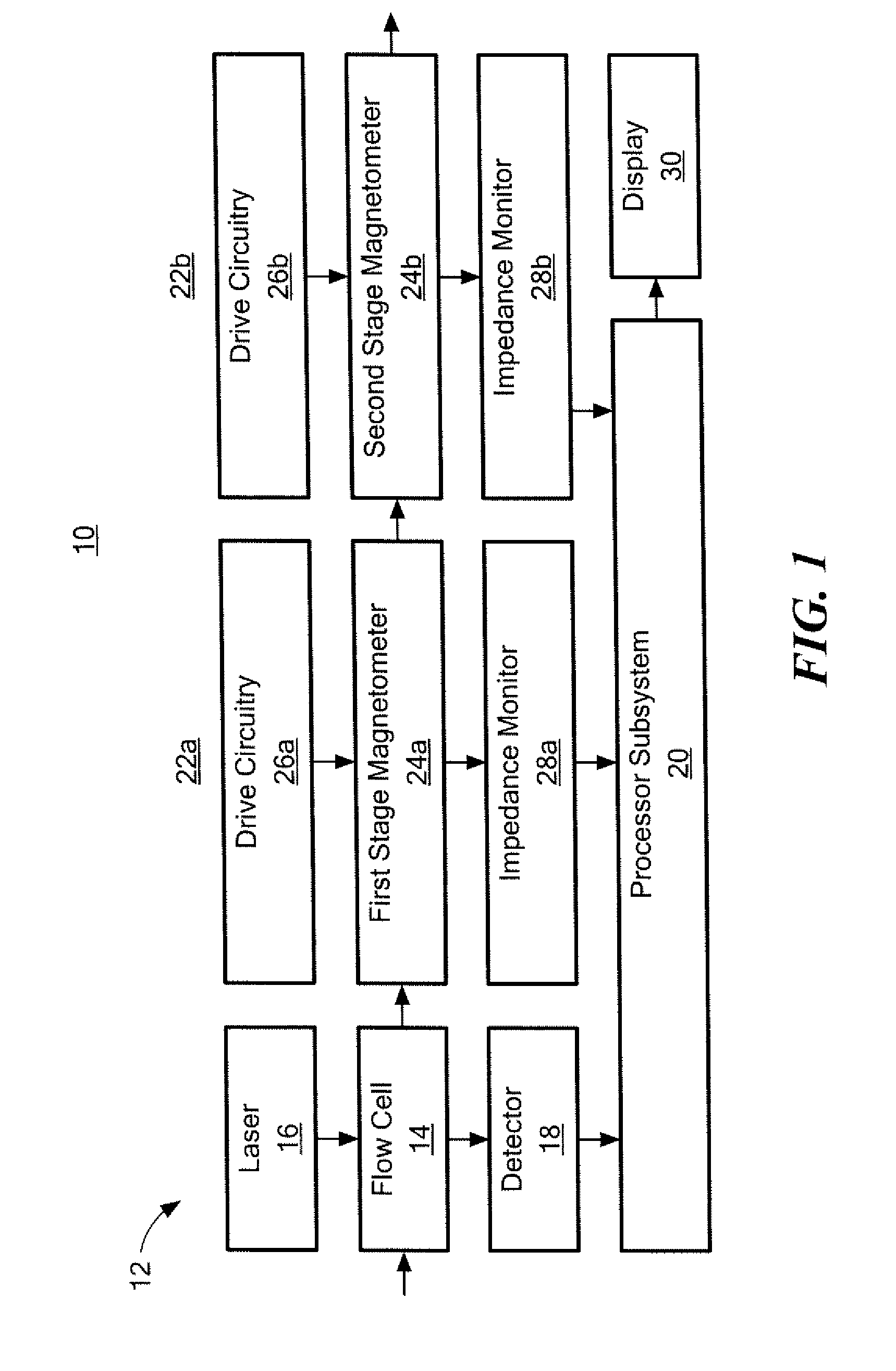
[0021]FIG. 1 depicts an example of a particle counter and classification system 10 including imaging subsystem 12 with flow cell 14 through which a fluid (e.g., oil) sample passes. The sample may be fluid diverted via a bypass conduit in a machine (e.g., engine or motor) or may be a sample obtained from a machine and delive...


PUM

PropertyMeasurementUnit
diameteraaaaaaaaaa
diameteraaaaaaaaaa
diameteraaaaaaaaaa

Abstract

A particle counter and classification system including an imaging subsystem configured to determine the size and morphology of particles above a predetermined size in a fluid in a sample cell. A first stage magnetometer sensor subsystem is tuned to detect and determine the size of ferrous and / or conducting particles. An optional second stage magnetometer sensor subsystem is tuned to detect the overall ferrous particle content of the fluid. A processor subsystem is configured to calculate and report the number of particles in the fluid in a plurality of size ranges, their morphology, their classification as a particular particle type according to their characteristic morphology, the number of ferrous and / or conducting particles, and the overall ferrous content of the fluid.

Description

FIELD OF THE INVENTION[0001]This invention relates to particle counters, magnetometers, and the classification of particulate in a fluid via particle imaging.BACKGROUND OF THE INVENTION[0002]The number of particles in a fluid sample, their size, and shape (morphology) can be determined by an imaging apparatus as shown, for example, in U.S. Pat. Nos. 5,572,320; 7,385,694; 5,627,905; 5,959,668; 6,049,381; 6,104,483; 6,501,504; 6,873,411; 7,019,834; 7,184,141; 7,307,717; 7,385,694; 7,921,739; 8,056,400 and 8,079,250 all incorporated herein by this reference. There is typically, however, no differentiation made between magnetic and non-magnetic particles. This information is important to maintenance personnel.[0003]Magnetometers can be used to determine the overall percent of ferromagnetic particles in oil, or to provide information regarding the size and magnetic nature (ferromagnetic or non-ferromagnetic) of individual particles greater than a certain minimum size threshold. See, for ...

Claims


Application Information

Patent Timeline
Patent Type & Authority Applications(United States)
IPC IPC(8): G01N15/10G01N15/06
CPCG01N15/10G01N2015/1087G01N2015/0693G01N15/0656G01N2015/0053G01N15/02G01N2015/0294G01N2015/1093G01N2015/1493G01N2015/1497G01N15/1459G01N15/1031G01N15/1463G01N33/2858
Inventor HENNING, PATRICK F.OLSON, ERIC J.GLABERSON, JOHN
Owner SPECTRO SCI INC
Why Eureka
Try Eureka