Method and apparatus for generating plasma

a plasma and plasma technology, applied in the field of plasma assisted deposition and processing, can solve the problems of non-homogeneous film growth, self-limiting thin-film growth, and not optimized for flow dynamics, so as to facilitate process control, improve the uniformity of growing films, and reduce the time of ald cycle

Inactive Publication Date: 2011-01-06
BENEQ OY
View PDF9 Cites 180 Cited by
  • Summary
  • Abstract
  • Description
  • Claims
  • Application Information

AI Technical Summary

Benefits of technology

[0016]By leading all the reactants in a process across the substrate and the reaction space in a cross flow geometry, i.e. across the substrate in a direction essentially parallel to the inner surface of the lower wall of the reaction space, the time of the ALD cycle may be reduced as opposed to a showerhead flow geometry. This results from the faster dynamics in the cross flow pattern where reactants flow through the reaction chamber as a travelling wave. This also enables the reactants to be spread similarly over the substrates, which facilitates process control as flow dynamics do not have to be optimized differently for different reactants. This leads to improved uniformity in the growing film. The optimization of flow dynamics and flow patterns of the reactants is especially important for processes using plasma since the high reactivity of plasma and radicals may cause nonuniformities in the growing film even with relatively small variations in concentration on the surface of the substrate.
[0017]In another embodiment of the present invention the reaction chamber comprises a second electrode located below the upper wall of the reaction chamber within the reaction chamber and a second inlet in a flow connection with a gas source and isolated from a flow connection with the sources for the reactants outside the reaction chamber. The second inlet is positioned to lead the gas into the space in between the second electrode and the lower wall through at least one hole in the second electrode in a direction essentially perpendicular to the inner surface of the lower wall. The second inlet leading gas into the reactio

Problems solved by technology

This results in self-limiting growth of the thin-film as only the following pulse of reactant of a different species is able to adsorb on the substrate.
Although an ALD process ideally produces one monolayer of conformal film in one pulsing cycle and although the process is less sensitive to flow dynamics than various Chemical Vapour Deposition (CVD) processes there exist many nonidealities which result in nonhomogeneous film growth if reactants are not uniformly distributed over the substrates.
A problem associated with state of the art ALD reaction chamber designs for generating capacitively coupled plasma is that they are not optimized for flow dynamics.
Different reactants follow

Method used


Image

  • Method and apparatus for generating plasma
  • Method and apparatus for generating plasma
  • Method and apparatus for generating plasma

Examples


Embodiment Construction

[0031]In the following, the present invention will be described in more detail with references to the accompanying figures, in which

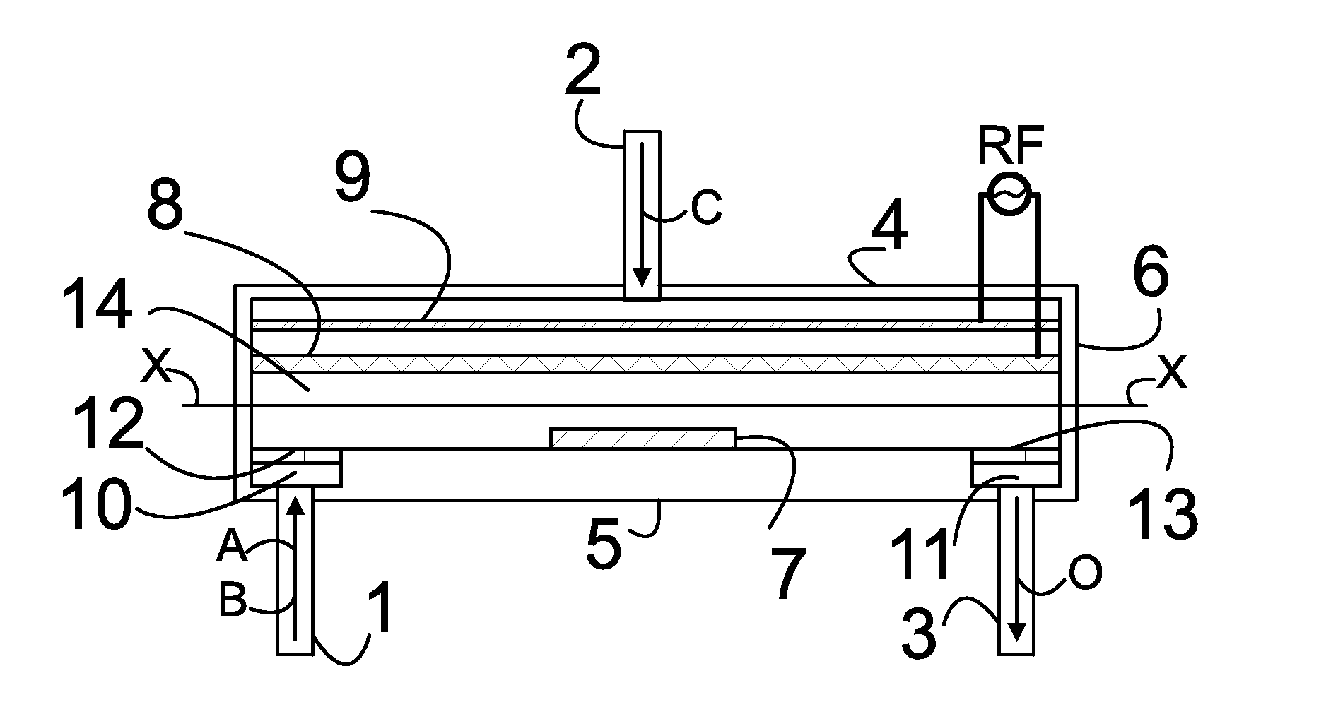
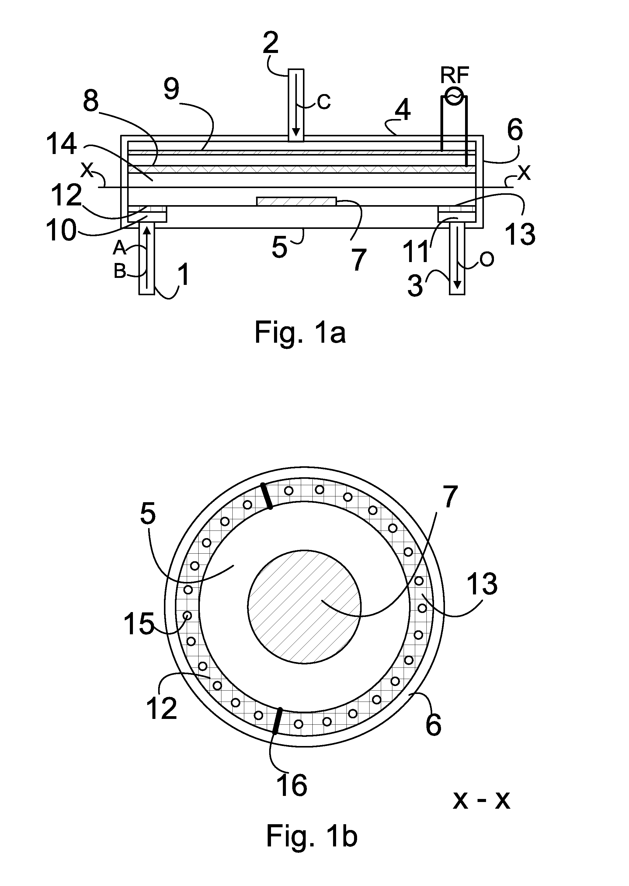
[0032]FIG. 1a is a schematic illustration of a cross section of a reaction chamber according to one embodiment of the present invention,

[0033]FIG. 1b schematically presents a cross-section of the reaction chamber illustrated in FIG. 1a,

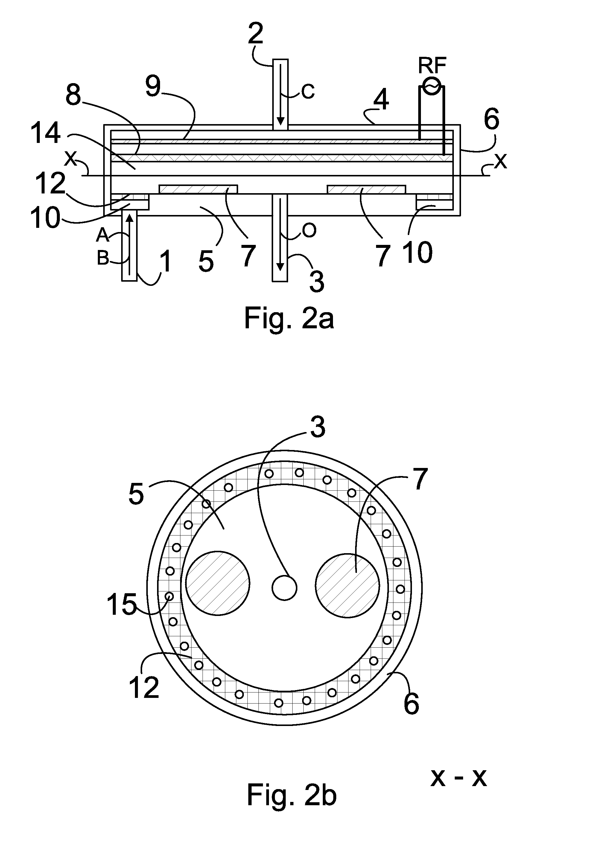
[0034]FIG. 2a is another schematic illustration of a cross section of a reaction chamber according to one embodiment of the present invention,

[0035]FIG. 2b schematically presents a cross-section of the reaction chamber illustrated in FIG. 2a.

[0036]FIG. 3a is another schematic illustration of a cross section of a reaction chamber according to one embodiment of the present invention,

[0037]FIG. 3b schematically presents a cross-section of the reaction chamber illustrated in FIG. 3a and

[0038]FIG. 4 is a flow-chart illustration of a method according to one embodiment of the present invention.

[0039]Unless stated otherwise, th...


PUM

PropertyMeasurementUnit
Fractionaaaaaaaaaa
Fractionaaaaaaaaaa
Lengthaaaaaaaaaa

Abstract

A reaction chamber of a reactor for coating or treating a substrate by an atomic layer deposition process (ALD) by exposing the substrate to alternately repeated surface reactions of two or more gas-phase reactants. The reaction chamber is configured to generate capacitively coupled plasma and comprises a reaction space within said reaction chamber, a first inlet to guide gases into the reaction chamber and an outlet to lead gases out of the reaction chamber. The reaction chamber is configured to lead the two or more reactants into the reaction chamber such that the two or more reactants may flow through the reaction space across the substrate in a direction essentially parallel to the inner surface of the lower wall.

Description

FIELD OF THE INVENTION[0001]The present invention relates to film deposition and processing technology. Especially the present invention relates to a method and an apparatus for plasma assisted deposition and processing.BACKGROUND OF THE INVENTION[0002]Atomic Layer Deposition (ALD) is a well known method to deposit uniform thin-films over substrates of various shapes, even over complex 3D structures. The substrates over which the thin-film is to be deposited are placed in a reaction chamber of an ALD reactor for processing. In an ALD process two or more different reactants (also called precursors or precursor materials) are introduced to the reaction chamber in a sequential manner and the reactants adsorb on surfaces e.g. on the substrate with suitable surface energy. In between each reactant pulse there is a purging period during which a flow of inert gas, often called the carrier gas, purges the reaction chamber from e.g. surplus reactants and by-products resulting from the adsorp...

Claims


Application Information

Patent Timeline
IPC IPC(8): C23C16/00H05H1/24
CPCC23C16/45536H01J37/32587H01J37/32091C23C16/45544C23C16/505
Inventor SOININEN, PEKKASNECK, SAMICAMERON, DAVID
Owner BENEQ OY
Why Eureka
Try Eureka