Atmospheric pressure molecular layer CVD

Inactive Publication Date: 2005-04-21
SELITSER SIMON I
View PDF25 Cites 263 Cited by
  • Summary
  • Abstract
  • Description
  • Claims
  • Application Information

AI Technical Summary

Benefits of technology

[0020] It is another object of the present invention to provide an atomic or molecular layer deposition apparatus operated at atmospheric pressure and capable of depositing sequentially different thin films substantially free of contamination by using separate chambers for each reactant. Separate deposition chambers for each reactant will greatly reduce or almost eliminate deposition of other reactant species on the chamber walls therefore removing a major source of contaminates and particles. Process conditions in each chamber can be individually adjusted to fit physical and chemical processes that take place in each chamber. For example, different temperature can be used for associative and dissociative chemisorptions, for red

Problems solved by technology

CVD deposition rates can be surface-limited at lower temperatures, or flux-limited at higher temperatures where deposition rates are relatively higher.
As is well known to those skilled in the art, ALCVD suffers from the disadvantage of an unacceptably high level of residual species (such as chlorine, fluorine or carbon) being retained in the film as well as possible formation of pinholes.
For such applications as gate dielectric and diffusion barriers, where the excellent uniformity conformal coatings achievable with ALCVD are most suitable and very low deposition rate is tolerable, chlorine, fluorine and carbon impurities are a major problem on the way to IC industry acceptance.
Gate dielectrics, which can be as thin as 10-60 Å, are especially susceptible to contamination.
The resultant contaminants cause the normally insulating gate oxide layer to become slightly conductive, e.g. having intolerably high leakage current, thus being unable to function as a gate dielectric.
The presence of impurities in diffusion barrier or gate dielectric not only affect their own properties, but also can adversely change the

Method used


Image

  • Atmospheric pressure molecular layer CVD
  • Atmospheric pressure molecular layer CVD
  • Atmospheric pressure molecular layer CVD

Examples


embodiment 100

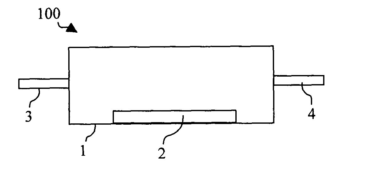
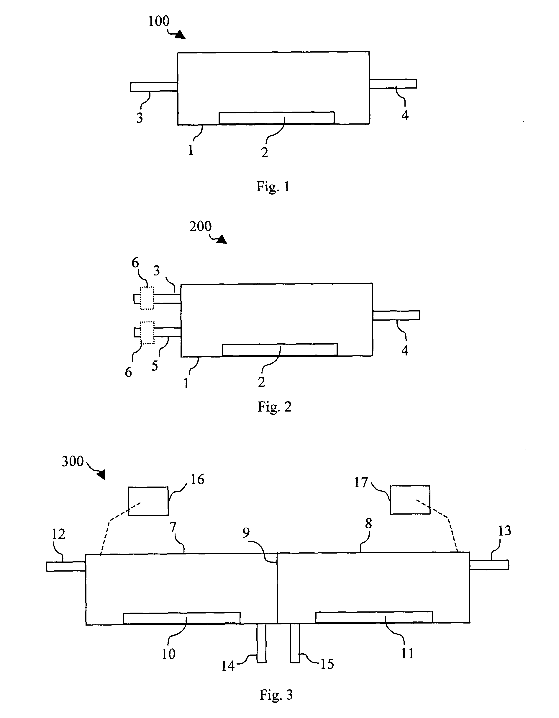
[0035]FIG. 1 is cross-sectional schematic view of an embodiment 100 of the present invention, having a chamber 1 which is capable for operation at atmospheric pressure and deposition of one monolayer per cycle. Heated substrate holder 2 located inside of the chamber and can be set for any temperature in the range of 50-800 0C. Reactant gasses and purge gas (not shown) are introduced to the chamber 1 through manifold 3. Reaction at atmospheric pressure between reactants is much more vigorous than at low pressure. Special precaution is taken to prevent any residue to remain in the chamber, manifolds, valves, etc., at the completion of a mono-layer deposition cycle by flushing out the chamber, manifolds, valves, etc., by a purge gas cycle.

[0036] Reactant and purge gasses in the embodiment 100 leave the chamber 1 through exhaust 4. To assist in evacuation of residual chemicals during each purging cycle, exhaust 4 can be optionally maintained at differential pressure compare to the chamb...

embodiment 200

[0038] A second reactant, purging manifold 3 is provided to deliver reactant and purging gas to chamber 2 in an alternative dual reactant / purge process using the embodiment 200. Purging gas is run through both manifolds 3, 5 simultaneously during a purging cycle in a dual reactant, purging process for embodiment 200. This will prevent reactant residue from remaining in stagnant areas of the reactant manifolds 3, 5.

[0039] A radical generator 6 (dotted lines) operating at atmospheric pressure can be, optionally, added to one or both manifolds. Such a radical generator can be e.g., an inductive thermal plasma torch, a generator based on glow discharge, DC or RF arc, etc.

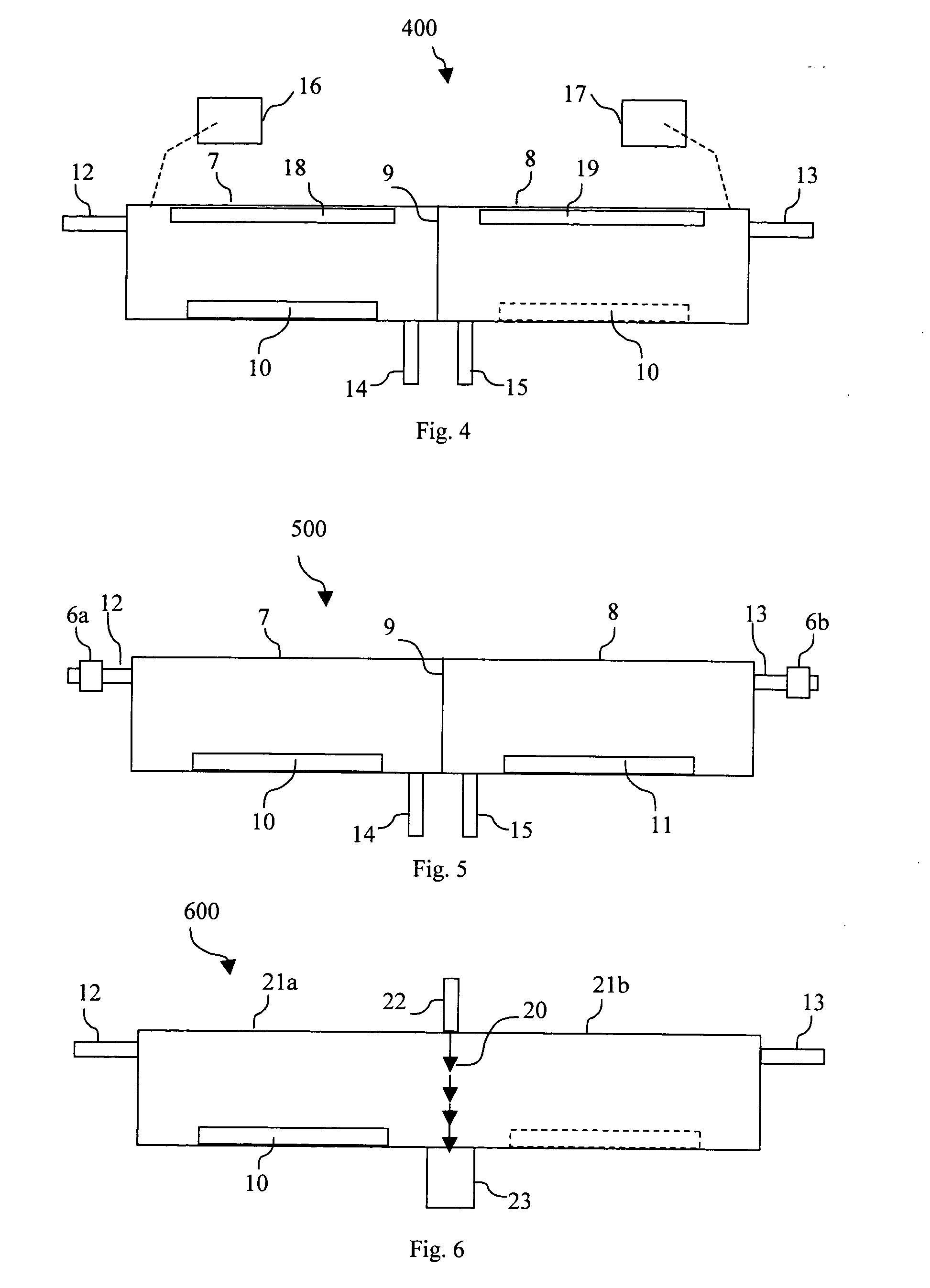
[0040]FIG. 3 is a schematic view of an embodiment 300 of the present invention apparatus that is capable of operation at atmospheric pressure and has a first chamber 7 and a physically separate second chamber 8. A solid wall 9 in embodiment 300 separates Chambers 7 and 8. Chambers 7 and 8 are each dedicated separately ...

embodiment 900

[0056] Referring now to FIG. 9, there is shown another embodiment 900 of the present invention. In some monolayer deposition processes situations it could be more beneficial to have not just one linear injector, but instead to have two or more per chamber. Embodiment 900 has such pairs of injectors in each chamber, i.e., a first injector 31a, and second injector 32a in the first chamber 28a and another first injector 31a, and another 2nd injector 32a in the second chamber 28ba. Purity and quality of the films deposited on substrates 26a -26f depends on a number of things, particularly how well the substrate surface is saturated with reactant in each chamber, the degree of completion of the chemisorptions at each available surface site and level of removing physisorbed reactant for the next chemisorption step, as we described above.

[0057] An additional process step that removes physisorbed reactant left after first injector, 31a, and −31f will greatly improve film quality. This is ac...


PUM

PropertyMeasurementUnit
Lengthaaaaaaaaaa
Volumeaaaaaaaaaa
Pressureaaaaaaaaaa

Abstract

An Atomic Layer CVD process and apparatus deposits single and or multiple minelayers of material sequentially at atmospheric pressure. Sequential monolayer depositions are separated in time and in space by combinations of physical barriers and/or gas curtains and/or by physical movement of substrates from one deposition chamber or location to another Pulse and/or continuous flows of reactant and purge gases are used in alternate embodiments of the present invention. Reactant injection, purge gas flow and exhaust flows at separated deposition chambers or locations are controlled by coordination of dedicated gas manifolds and control systems for each spatially or temporally separated deposition process or location.

Description

[0001] This application claims priority based on Provisional Application Ser. No. 60 / 402,871 Filing Date Aug. 13, 2002BACKGROUND OF THE INVENTION [0002] Atomic Layer Deposition (ALD) or Atomic Layer CVD (ALCVD) has been explored since the late 70's, mainly for formation of various compound semiconductor single-crystal materials, where it is valued for the ability to deposit good crystalline materials at unusually low temperature. The essence of the method is the use of adsorption to saturate the surface of a substrate with monolayer of one reactant, and then separately expose the surface to a second reactant, which reactivates the surface (and in the case of compound, may deposit a monolayer of the second constituent). [0003] In conventional CVD, all reactants required for film growth are simultaneously exposed to a wafer surface, where they continuously deposit a thin film. CVD deposition rates can be surface-limited at lower temperatures, or flux-limited at higher temperatures whe...

Claims


Application Information

Patent Timeline
IPC IPC(8): C23C16/00
CPCC23C16/45551C23C16/45519
Inventor SELITSER, SIMON I.
Owner SELITSER SIMON I
Why Eureka
Try Eureka