Method of moulding and a core plug for use in the method

Inactive Publication Date: 2015-10-22
AIRBUS OPERATIONS LTD
View PDF9 Cites 2 Cited by
  • Summary
  • Abstract
  • Description
  • Claims
  • Application Information

AI Technical Summary

Benefits of technology

[0012]In one embodiment, a coolant gas may be supplied through the piece of open cell foam prior to and/or during cutting in step (a), with the aim of making the material more rigid and easier to cut and/or manipulate.
[0013]In an alternative embodiment

Problems solved by technology

Due to limitations in the moulding process and the requirement to support a moulded component internally during curing, many products made from such materials are made from a number of individually molded parts or by co-bonding/curing pre-shaped ‘green’ or ‘uncured’ structures at the same time.
Although the use of fixings of the type normally associated with metall

Method used


Image

  • Method of moulding and a core plug for use in the method
  • Method of moulding and a core plug for use in the method
  • Method of moulding and a core plug for use in the method

Examples


Embodiment Construction

[0021]Embodiments of the invention will now be described, by way of example only, with reference to the accompanying drawings.

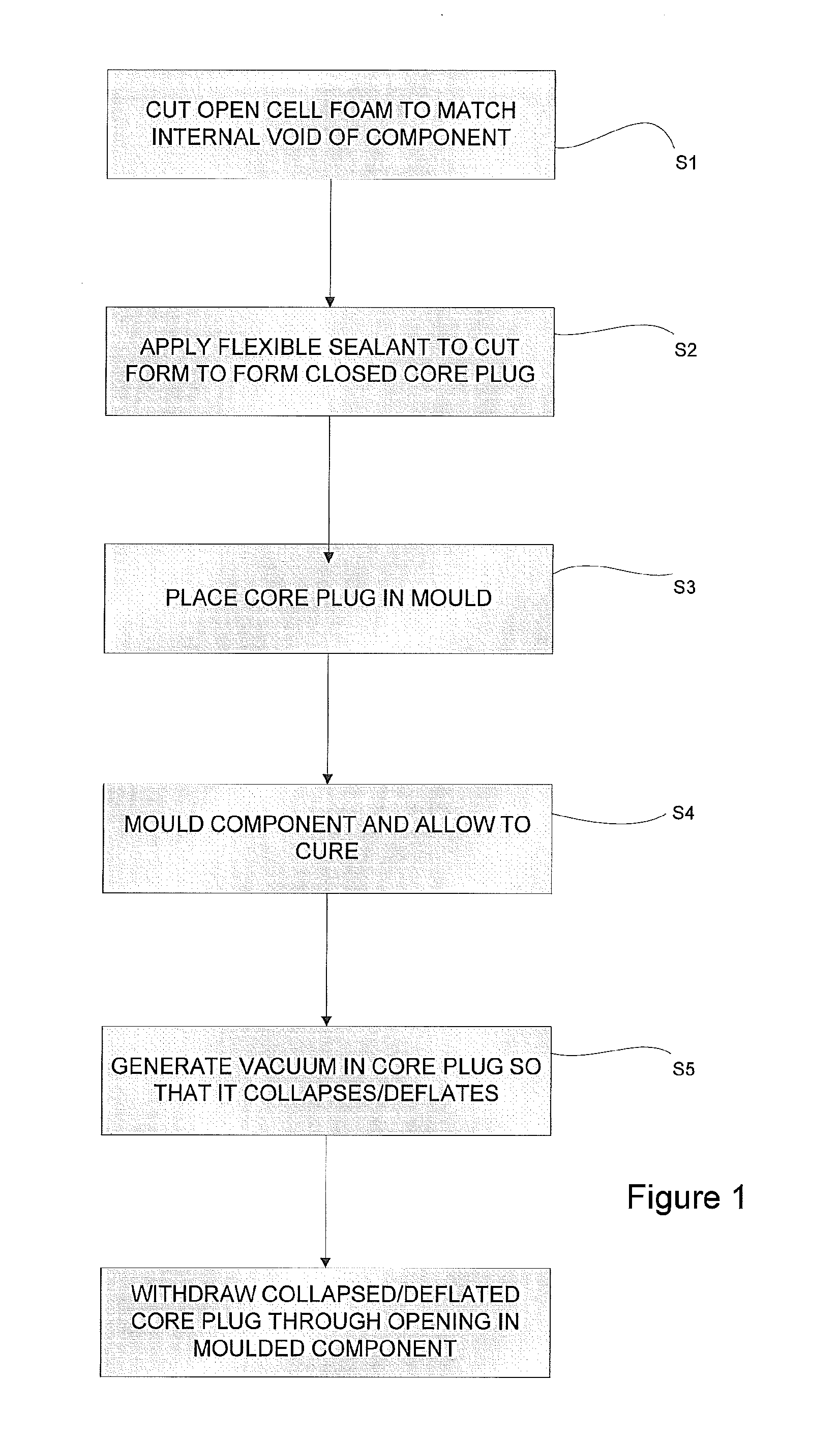
[0022]Embodiments of the present invention provide a method of moulding a CFRP or GFRP structural component having a closed shape and an internal void. The method includes the use of a collapsible foam core plug 1 to provide support to the component during moulding and curing whilst enabling the core plug 1 to be removed from the void once the component has cured and no longer needs to be supported.

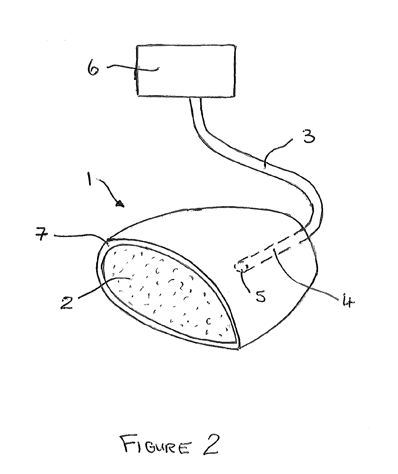
[0023]A cross-section through a core plug 1 is shown in FIG. 2. Whilst a core plug 1 of a particular shape to match the shape of a component to be moulded is illustrated in FIG. 1, it will be appreciated that the core plug 1 can take many different shapes and have many different forms. The core plug 1 has a core which is formed from an open cell foam material 2 that, after being compressed, quickly recovers its original dimensions due to its inherently resilient pr...


PUM

PropertyMeasurementUnit
Pressureaaaaaaaaaa
Sizeaaaaaaaaaa
Flexibilityaaaaaaaaaa

Abstract

A method of moulding a component having a closed shape and defining an internal void having a predetermined size and shape is disclosed, together with a core plug for use in the method. The method comprises the steps of: (a) cutting a piece of open cell foam material to substantially match said predetermined size and shape of the internal void of a component to be moulded; (b) applying a flexible sealant to an outer surface of said cut piece of resilient open cell foam to form a closed core; (c) placing said closed core in the mould to support a component during moulding and curing; (d) generating a vacuum within the closed core to collapse it within the void after the moulded component has cured, and (e) removing the collapsed core from the molded component through an opening in said moulded component.

Description

BACKGROUND TO THE INVENTION[0001]The present invention relates to a method of moulding a component. A core plug for use in the method is also disclosed.[0002]Light weight structures formed from CFRP (carbon fibre reinforced plastic) or GFRP (glass fibre reinforced plastic) are more commonly being used in marine, aeronautical and automotive applications. Due to limitations in the moulding process and the requirement to support a moulded component internally during curing, many products made from such materials are made from a number of individually molded parts or by co-bonding / curing pre-shaped ‘green’ or ‘uncured’ structures at the same time. However, whilst co-bonding and curing results in a more integral structure, at least for those structures that have a closed shape, moulding in discrete sections is necessary so that a support structure located within the part, and which is used to support the component during the moulding and curing cycle, remains accessible and so can be rem...

Claims


Application Information

Patent Timeline
IPC IPC(8): B29C33/38
CPCB29L2022/00B29C33/3814B29C33/485B29C33/40B29C33/48B29C33/505
Inventor PARKER, SIMON
Owner AIRBUS OPERATIONS LTD
Why Eureka
Try Eureka