Method for connecting parts relative to one another

a technology of connecting parts and parts, applied in the field of mechanical engineering and construction, can solve the problems of excluding the possibility of cavity delimitation, and achieve the effect of reducing the strain of the second material

Active Publication Date: 2015-10-22
WOODWELDING
View PDF1 Cites 11 Cited by
  • Summary
  • Abstract
  • Description
  • Claims
  • Application Information

AI Technical Summary

Benefits of technology

[0038]In a group of embodiments, the second part has a core of a material not liquefiable under the conditions that are present during the process (and, for example, especially not at temperatures below 450° C. or 350° C. or below 250° C.) and further has thermoplastic material around the core. In these embodiments, the arrangement of the thermoplastic material and the conditions during casting may be chosen so that after the process there is no direct physical contact between the core and the first part. The thermoplastic material forms a barrier between the core and the first part. This barrier has the possible advantage of having the potential to damp any mechanical shock and / or vibration acting on the first part or on the core with respect to the core or the first part, respectively. Also, the barrier may serve as barrier against corrosion.
[0039]In addition to damping, the thermoplastic material also ensures a uniform distribution of the stress if the connection is subject to a mechanical load. Stress calculations have shown that compared to a conventional screw, a the stress on the second material and consequently the strain of the second material may be reduced by using a core covered with the thermoplastic material by up to between 75% and 90%.

Problems solved by technology

It does not, however, rule out the possibility that the cavity is delimited by a user-adjustable means, such as a movable piston.

Method used


Image

  • Method for connecting parts relative to one another
  • Method for connecting parts relative to one another
  • Method for connecting parts relative to one another

Examples


Embodiment Construction

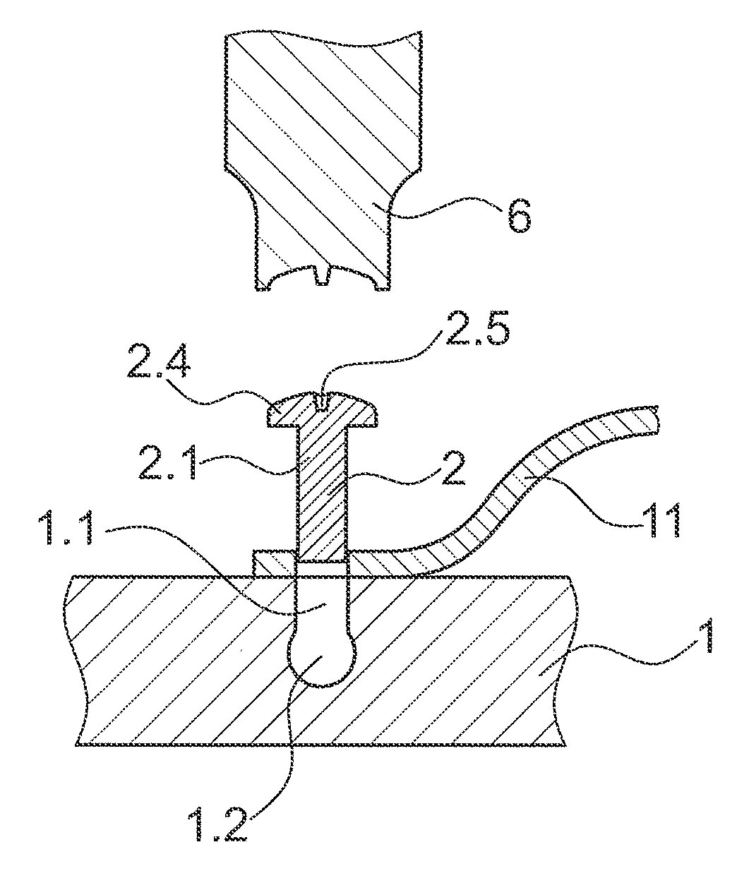
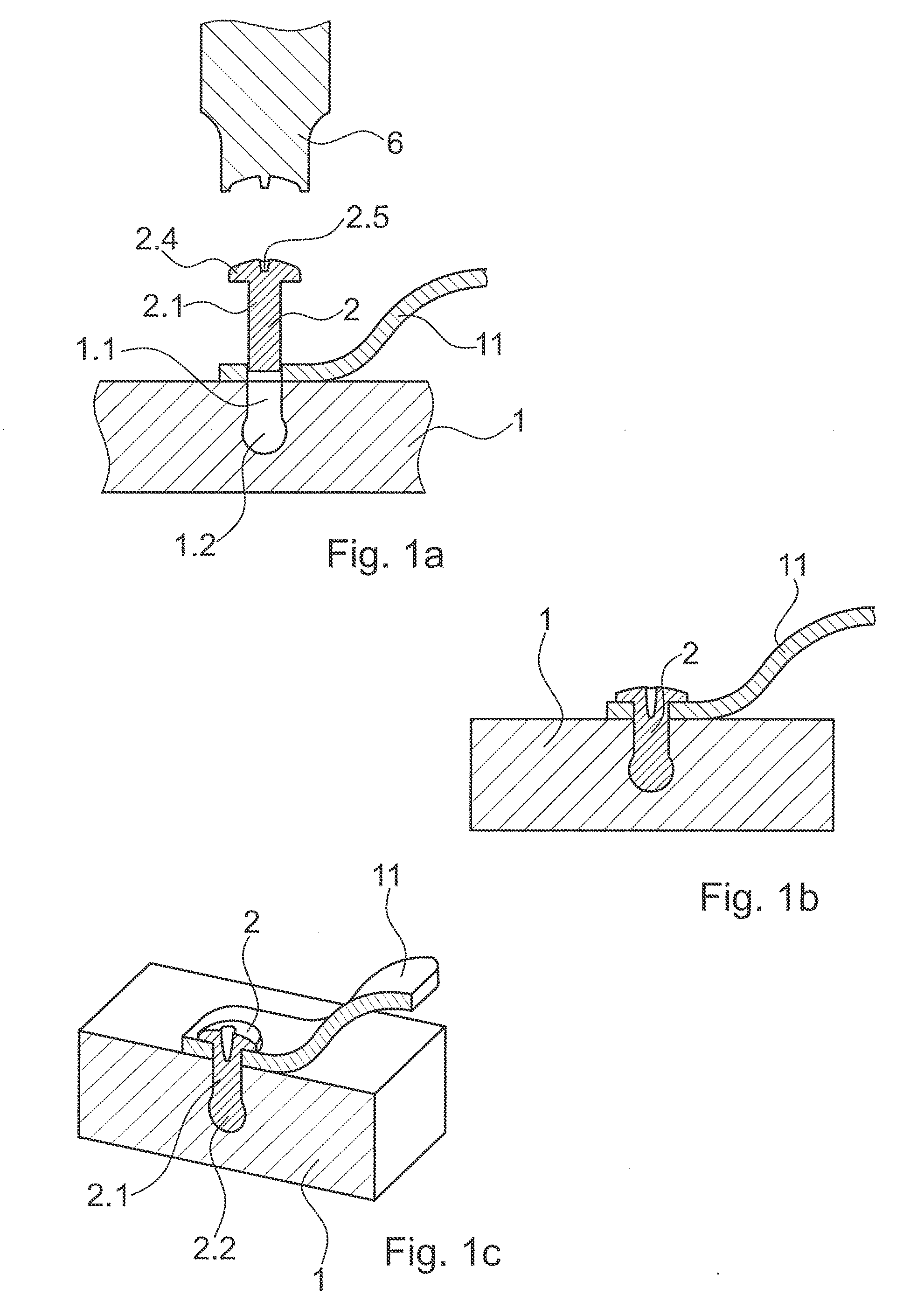
[0062]FIG. 1a shows a basic configuration with a first part having an opening with a shaft portion 1.1 and a broadening portion 1.2 defining an undercut. A second part 2 in the depicted configuration consists of thermoplastic material. The second part has a shaft portion 2.1 and a proximal head 2.4 with a guiding indentation 2.5. The sonotrode (or horn) 6 has a shape adapted to the shape of the head portion. A further element 11 to be connected to the first part 1 is depicted with a through-going hole.

[0063]The initial head portion 2.4 is optional. Alternatively to the second part having such a head portion, such portion may be shaped in the casting process after liquefaction of the thermoplastic material in the vicinity to the sonotrode 6. Also, further alternatives exist.

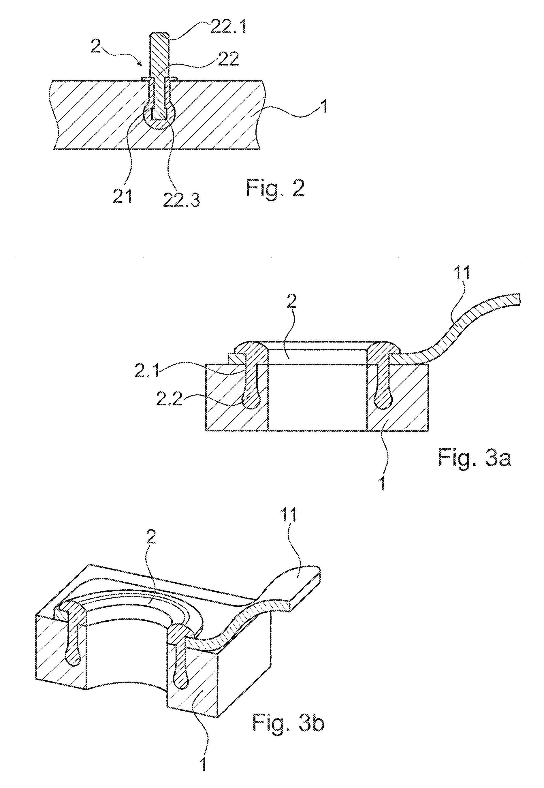
[0064]For the casting process, the sonotrode 6 presses the second part 2 into the opening and couples vibrations into the second part, whereby the distal end face is pressed against the bottom of the opening. Due ...


PUM

PropertyMeasurementUnit
volume fractionaaaaaaaaaa
temperaturesaaaaaaaaaa

Abstract

A method of connecting parts relative to one another includes the steps of providing a first part, the first part having an opening; providing a second part, the second part having thermoplastic material in a solid state; arranging the first part and the second part relative to one another, so that the second part reaches into the opening, while a volume with an undercut is defined in the opening; causing a mechanical pressure and mechanical energy to act on the second part until at least a part of the thermoplastic material is caused to liquefy and to fill the volume; and causing the thermoplastic material to re-solidify, thereby anchoring the second part in the first part.

Description

BACKGROUND OF THE INVENTION[0001]1. Field of the Invention[0002]The invention is in the fields of mechanical engineering and construction, especially mechanical construction, for example automotive engineering, aircraft construction, shipbuilding, machine construction, toy construction etc.[0003]2. Description Of Related Art[0004]In engineering and construction, there is still room of improvement for the fixation of parts relative to one another. For example, in automotive aircraft, shipbuilding and machine construction industries, metallic or ceramic parts manufactured by different techniques have to be connected to one another. For example, in automotive industry spaceframe connections of beams and pressure die cast parts are crucial for the stability of the automobile's frame.[0005]Known connectors are bolts, screws and rivets. These are well established. However, the stress induced in the connected parts by, for example, a screw connection is significant. Also, when the manufact...

Claims


Application Information

Patent Timeline
Patent Type & Authority Applications(United States)
IPC IPC(8): F16B3/00B29C65/60B29C65/08
CPCF16B3/00B29L2031/30B29C65/601B29C65/08B29C65/603B29C65/604B29C66/112B29C66/1122B29C66/131B29C66/474B29C66/7392B29C66/8322B29C70/845F16B3/005B29C65/02B29C66/81423B29C66/81429B29C66/742B29C66/304B29C66/721B29C66/342B29C66/45B29C2043/3266B29L2031/3076B29L2031/737B29C43/18B29C66/71B29C66/81431B29K2023/06B29K2023/12B29K2025/06B29K2025/08B29K2027/06B29K2033/12B29K2055/02B29K2059/00B29K2067/00B29K2069/00B29K2071/00B29K2075/00B29K2077/00B29K2079/085
Inventor MAYER, JORGLEHMANN, MARIOWENGER, ANDREAS
Owner WOODWELDING
Why Eureka
Try Eureka