Drive device

Active Publication Date: 2015-10-22
STABILUS
View PDF0 Cites 11 Cited by
  • Summary
  • Abstract
  • Description
  • Claims
  • Application Information

AI Technical Summary

Benefits of technology

[0023]This configuration has the same advantages as the drive device previously discussed, wherein the quantity of parts is further reduced so that the constructional size of the drive device and the assembly effort for the drive device are reduced even more.
[0024]The first cylindrical element which is fixedly connected to the thre

Problems solved by technology

A problem in drives without brake devices is that the stop position into which the movable component part has been moved cannot be maintained due to unwanted inherent dy

Method used


Image

  • Drive device
  • Drive device
  • Drive device

Examples


Example

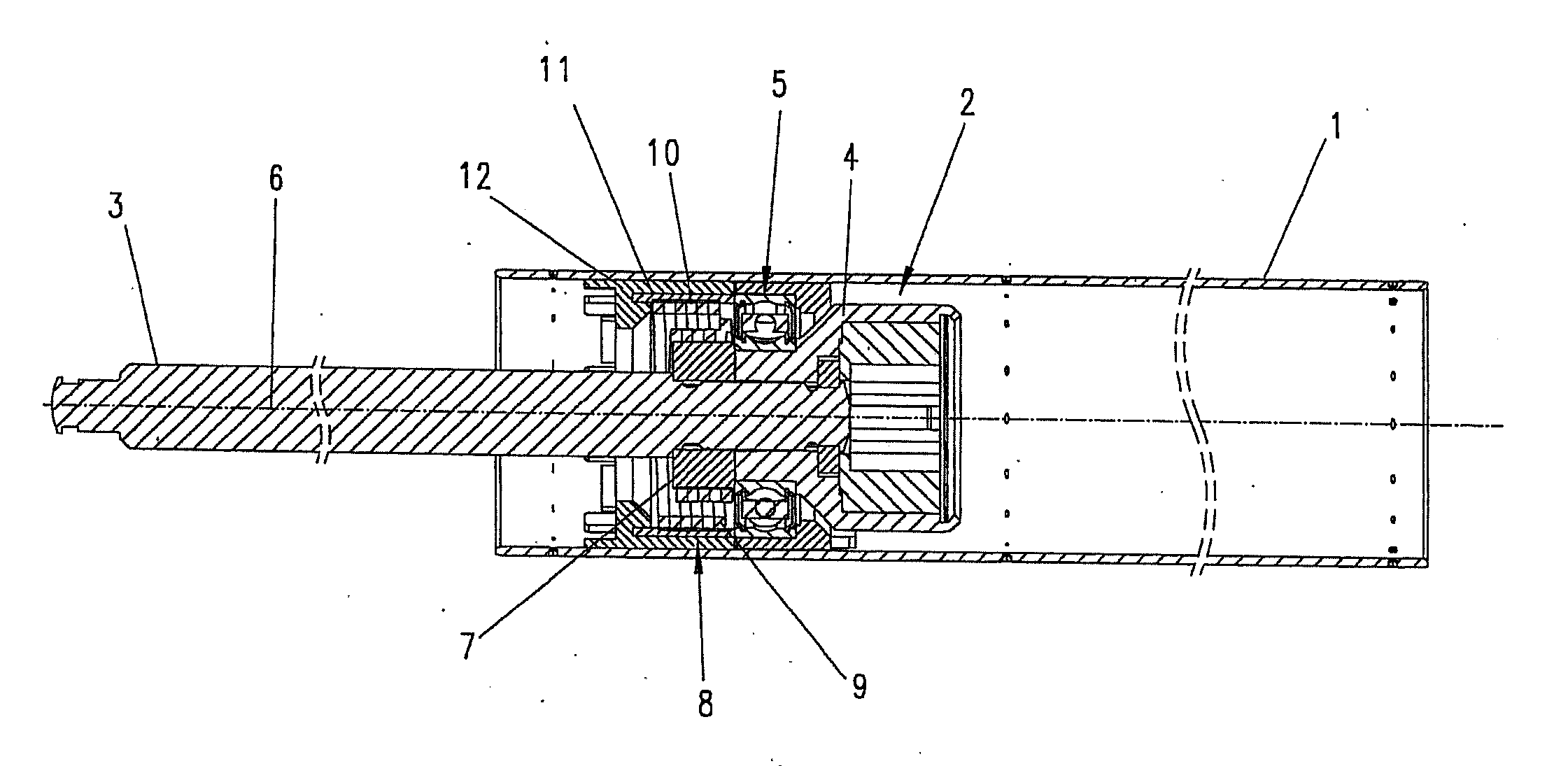
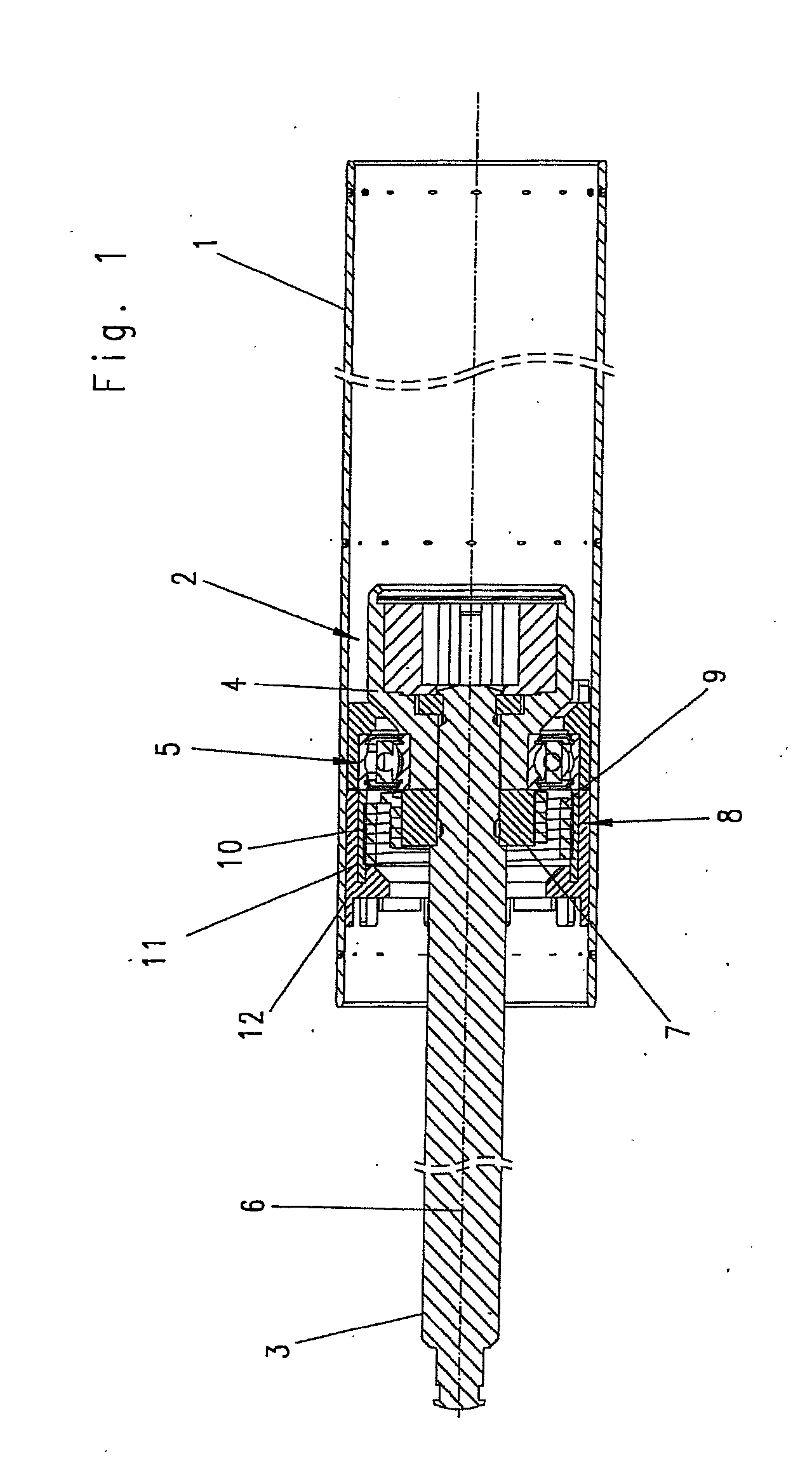
[0042]The depicted drive devices have a tubular housing 1 in which is arranged a reversible electric motor, not shown, by which a threaded spindle 3 of a spindle drive can be driven in rotation around an axis of rotation 6 via a clutch 2.

[0043]The threaded spindle 3 projects by its end on the motor side into a corresponding coaxial recess of a rotatably drivable clutch part 4 which is rotatably supported in the housing 1 via a grooved ball bearing 5.

[0044]A spindle nut, not shown, of the spindle drive is arranged on the threaded spindle 3.

[0045]A first component part and a second component part are drivable so as to be axially movable relative to one another by the spindle drive. The first component part can be arranged so as to be stationary and can be, e.g., a body of a vehicle. The second component part can be articulated at the second component part so as to be swivelable around a swiveling axis and can be a hatch of the vehicle.

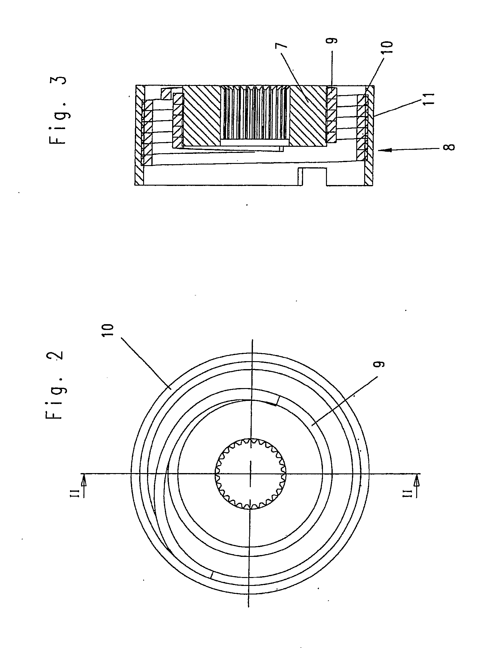
[0046]A hub 7 is fixedly arranged on the threaded ...


PUM


Abstract

A drive device has a spindle drive having a threaded spindle and a spindle nut arranged on the threaded spindle. The spindle drive is configured to drive a first component element and a second component element so as to be axially movable relative to one another. The spindle drive is reversibly rotatably drivable around an axis of rotation extending coaxial to the threaded spindle by a rotatably driven driveshaft arranged in a housing so as to be fixed with respect to rotation. A brake device prevents axially relative movement of the first component element and second component element relative to one another through axial application of force to the first component element and/or second component element.

Description

CROSS-REFERENCE TO RELATED APPLICATIONS[0001]This is a U.S. national stage of application No. PCT / EP2013 / 072831, filed on 31 Oct. 2013, which claims priority to the German Application No. DE 10 2012 110 505.7 filed 2 Nov. 2012, the content of both incorporated herein by reference.BACKGROUND OF THE INVENTION[0002]1. Field of the Invention[0003]The invention is directed to a drive device for a movable component part, with a first fastening element connectable to a stationary first component element and with a second component element movable axially relative thereto at the end opposite the first fastening element and which has, at its end opposite the first fastening element, a second fastening element that can be fastened to the movable component part, with a spindle drive having a threaded spindle and a spindle nut arranged on the threaded spindle, by which spindle drive the first component element and the second component element can be driven so as to be axially movable relative t...

Claims


Application Information

Patent Timeline
IPC IPC(8): F16H25/24F16D51/02E05F15/622
CPCF16H25/2454E05F15/622E05Y2900/546F16H2025/2463F16D51/02E05Y2201/49E05Y2800/205E05Y2800/22
Inventor RITTER, ANDREASBATOSKY, OLEGHILLEN, JORG
Owner STABILUS
Why Eureka
Try Eureka