Cryogenic gas circulation and heat exchanger

a cryogenic gas and heat exchanger technology, applied in the direction of refrigerating devices, stationary tubular conduit assemblies, lighting and heating apparatus, etc., can solve the problems of not providing the flow rate required, not convenient or possible in all applications, and not convenient or possible in particular placemen

Inactive Publication Date: 2015-10-22
VICTORIA LINK LTD
View PDF11 Cites 18 Cited by
  • Summary
  • Abstract
  • Description
  • Claims
  • Application Information

AI Technical Summary

Benefits of technology

[0012]This disclosure also provides a counter-flow heat exchanger especially adapted for circulating cryogenic gas between a room-temperature environment and a cryogenic environment in a cryogenic chamber. The heat exchanger includes an outer tube and an inner tube nested within the outer tube, and a pair of three-port connector fittings attached to respective ends of the tubes. The three-port connector fittings provide a sealed environment with independent access to a first flow of fluid and a second flow of fluid through the heat exchanger, while preventing mixing of the first flow of fluid and the second flow of fluid. The first flow of fluid flows between the three-port connector fittings inside the outer tube and outside the inner tube, and the second flow of fluid flows between the three-port connector fittings inside the inner tube. In a preferred embodiment, the tubes are wound into a helix for compactness.

Problems solved by technology

This particular placement may not be convenient or possible in all applications and also may not provide the flow rate required.

Method used


Image

  • Cryogenic gas circulation and heat exchanger
  • Cryogenic gas circulation and heat exchanger
  • Cryogenic gas circulation and heat exchanger

Examples


Embodiment Construction

[0018]It will be appreciated that for simplicity and clarity of illustration, where appropriate, reference numerals have been repeated among the different figures to indicate corresponding or analogous elements. In addition, numerous specific details are set forth in order to provide a thorough understanding of the embodiments described herein. However, it will be understood by those of ordinary skill in the art that the embodiments described herein can be practiced without these specific details. In other instances, methods, procedures and components have not been described in detail so as not to obscure the related relevant feature being described. Also, the description is not to be considered as limiting the scope of the embodiments described herein. The drawings are not necessarily to scale and the proportions of certain parts have been exaggerated to better illustrate details and features of the present disclosure.

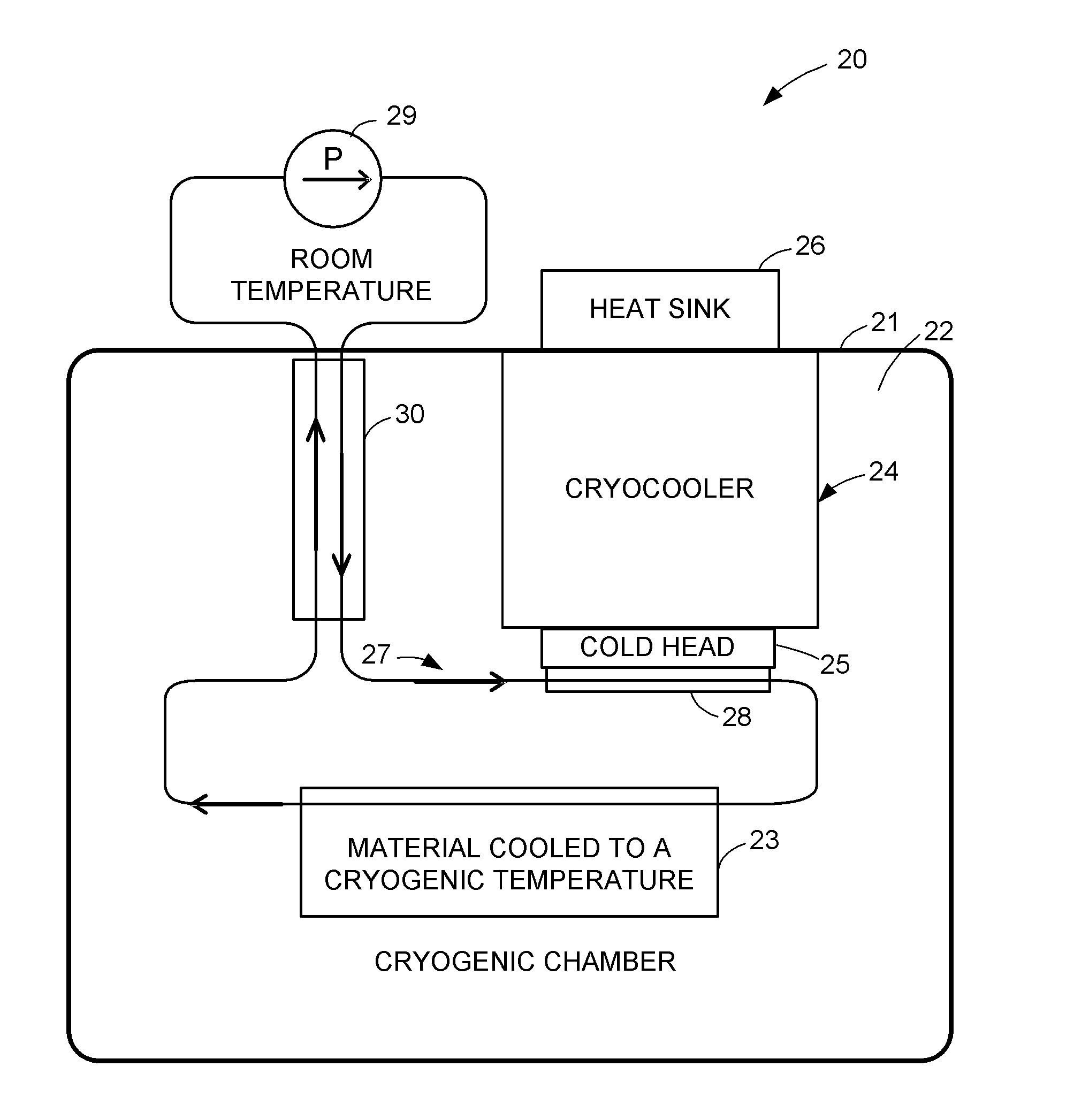
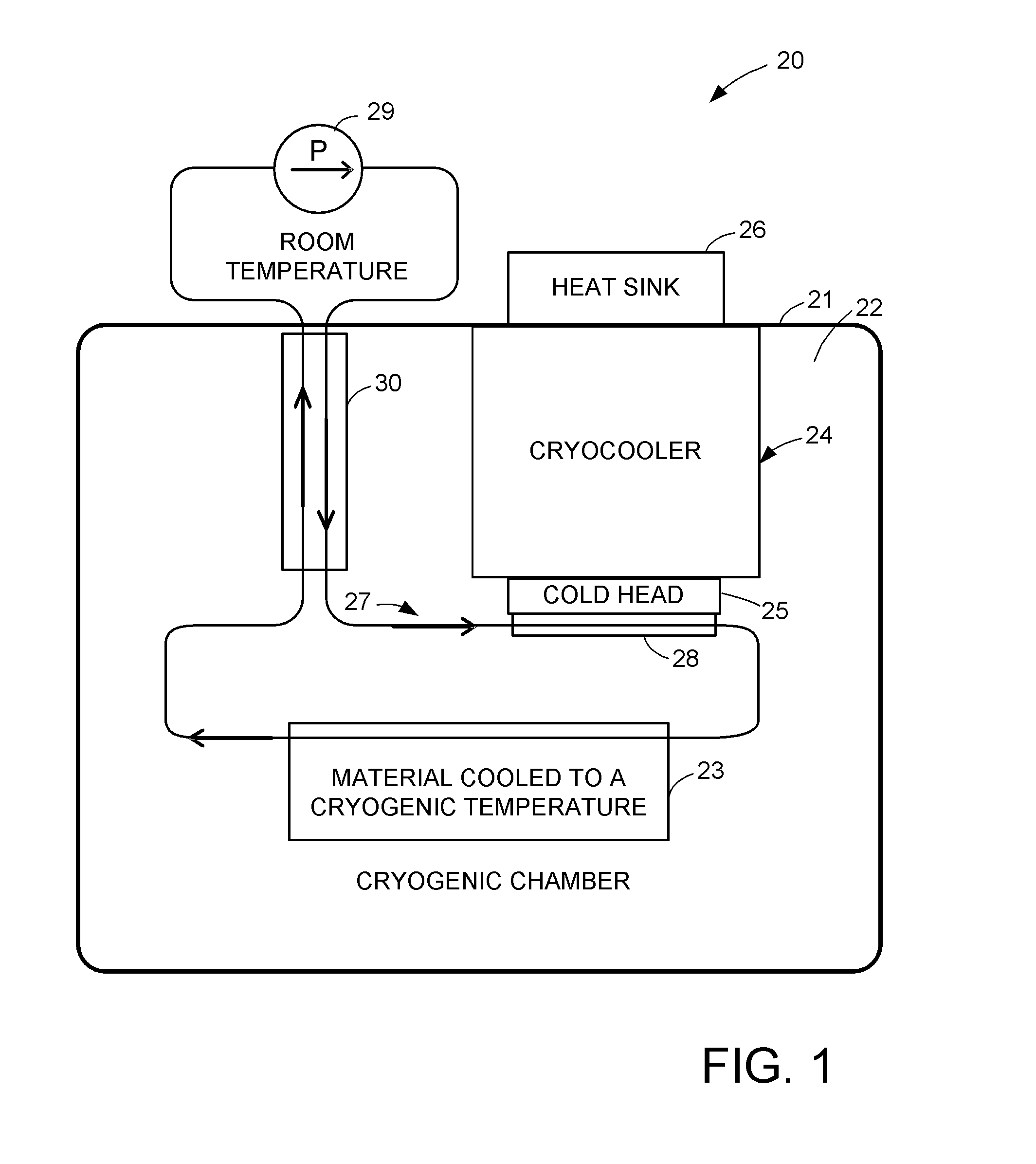
[0019]FIG. 1 shows a cryogenic system 20 including a housing 21 ...


PUM


Abstract

A cryogenic system includes a housing of a cryogenic chamber, a cold source in the cryogenic chamber, and a gas circulation loop for circulating cryogenic gas between the cold source and material to be cooled in the cryogenic chamber. The circulation loop includes a gas pump, and a counter-flow heat exchanger connecting the gas pump to the cold source for cooling an in-flow of the cryogenic gas from the gas pump to the cold source with an out-flow of the cryogenic gas from the material to be cooled to the gas pump. In a preferred construction, the heat exchanger includes an outer tube and an inner tube nested within the outer tube, and a pair of three-port connector fittings attached to respective ends of the tubes.

Description

RELATED APPLICATIONS[0001]The present application claims the benefit of Nick Strickland and Stuart Wimbush U.S. Provisional Application Ser. 61 / 980,337 filed Apr. 16, 2014, incorporated herein by reference.TECHNICAL FIELD[0002]This disclosure relates to circulation of cryogenic gas in a cryogenic system, and a heat exchanger especially adapted for use in such a cryogenic system.BACKGROUND[0003]A cryogenic system often includes material to be cooled to a cryogenic temperature, a cryocooler for cooling the material to the cryogenic temperature, and a means for transporting heat from the material to the cryocooler. The means for transporting heat from the material to the cryocooler may include a gas circulation loop. For example, the material to be cooled to cryogenic temperature is a sample of material under analysis while properties of the material are measured as a function of temperature. In another example, the material to be kept at cryogenic temperature is a superconducting comp...

Claims


Application Information

Patent Timeline
Patent Type & Authority Applications(United States)
IPC IPC(8): F25D3/00F25D17/06F25D23/00F28D7/10
CPCF25D3/005F25D23/006F25D17/06F28D7/10F25B9/10F25B25/005F25D19/006F28D7/106F28D7/14F28D2021/0033
Inventor STRICKLAND, NICHOLASWIMBUSH, STUART
Owner VICTORIA LINK LTD
Why Eureka
Try Eureka