
Method for checking the compliance of an optical characteristic of an ophthalmic lens and associated device

Active Publication Date: 2015-10-22
ESSILOR INT CIE GEN DOPTIQUE
View PDF0 Cites 29 Cited by
  • Summary
  • Abstract
  • Description
  • Claims
  • Application Information

AI Technical Summary

Benefits of technology

The invention describes a method for checking the optical characteristics of ophthalmic lenses by using a deformed test pattern that contains information about the expected optical characteristics. This allows the optician to quickly determine if the verified optical characteristic is conforming to the expected one. This method prevents errors by reducing the number of original test patterns that need to be tested and minimizing handling problems. The invention also provides a device that facilitates the use of the verification method.

Problems solved by technology

This is all the more true since ophthalmic lenses have optical characteristics that are increasingly complex due to the development of ophthalmic lenses of personalized design.
Nevertheless, this type of apparatus is very sensitive to the centering of the ophthalmic lens on a holder of the apparatus and it allows power to be measured only locally, typically in a limited zone of about 5 to 10 millimeters (mm).
Electronic lensmeters of the “lens-mapper” type produce a complete map of the optical powers of the ophthalmic lens but are in general expensive and difficult to use.
The measurement method of document EP 1 324 015 therefore requires two separate grids to be used, each of which is imaged through the ophthalmic lens to be measured, thereby making its implementation difficult.
However, this type of means is easily falsifiable and does not guarantee a satisfactory level of security.

Method used


Image

  • Method for checking the compliance of an optical characteristic of an ophthalmic lens and associated device
  • Method for checking the compliance of an optical characteristic of an ophthalmic lens and associated device
  • Method for checking the compliance of an optical characteristic of an ophthalmic lens and associated device

Examples


first embodiment

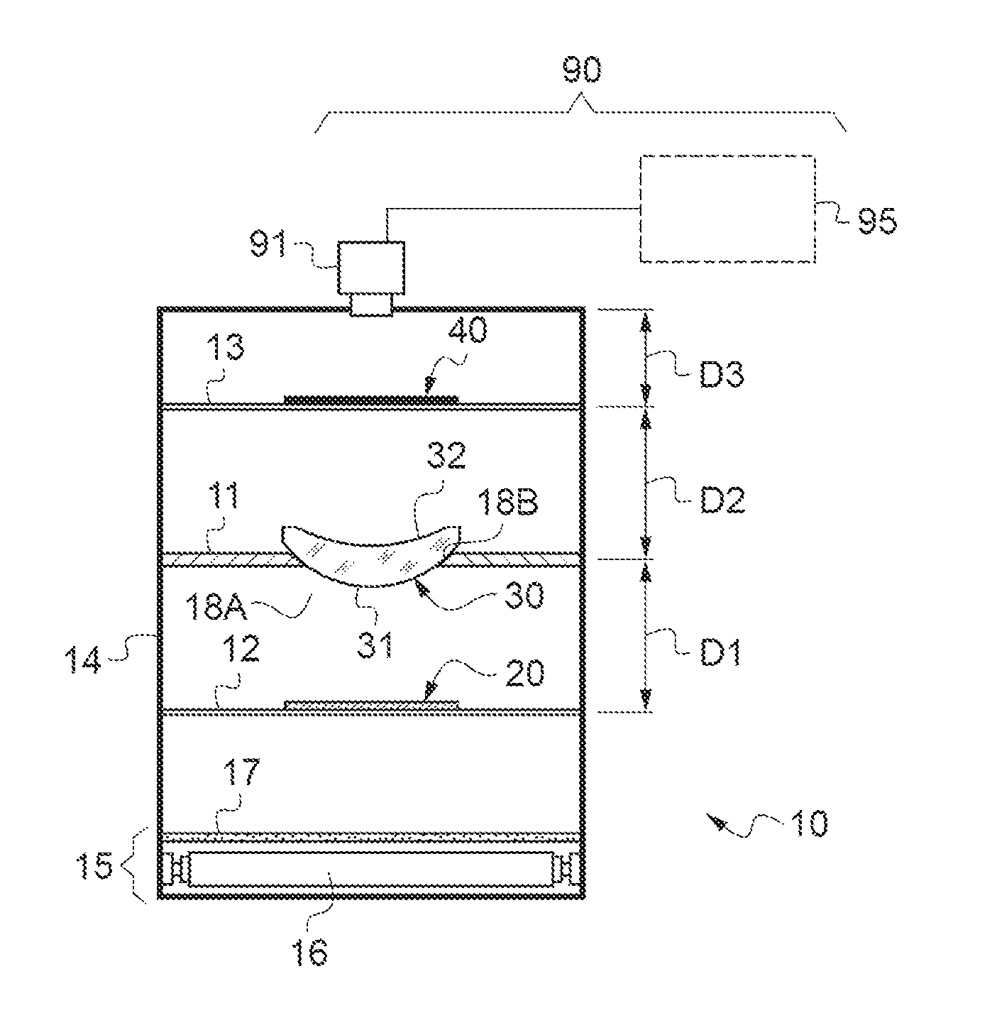
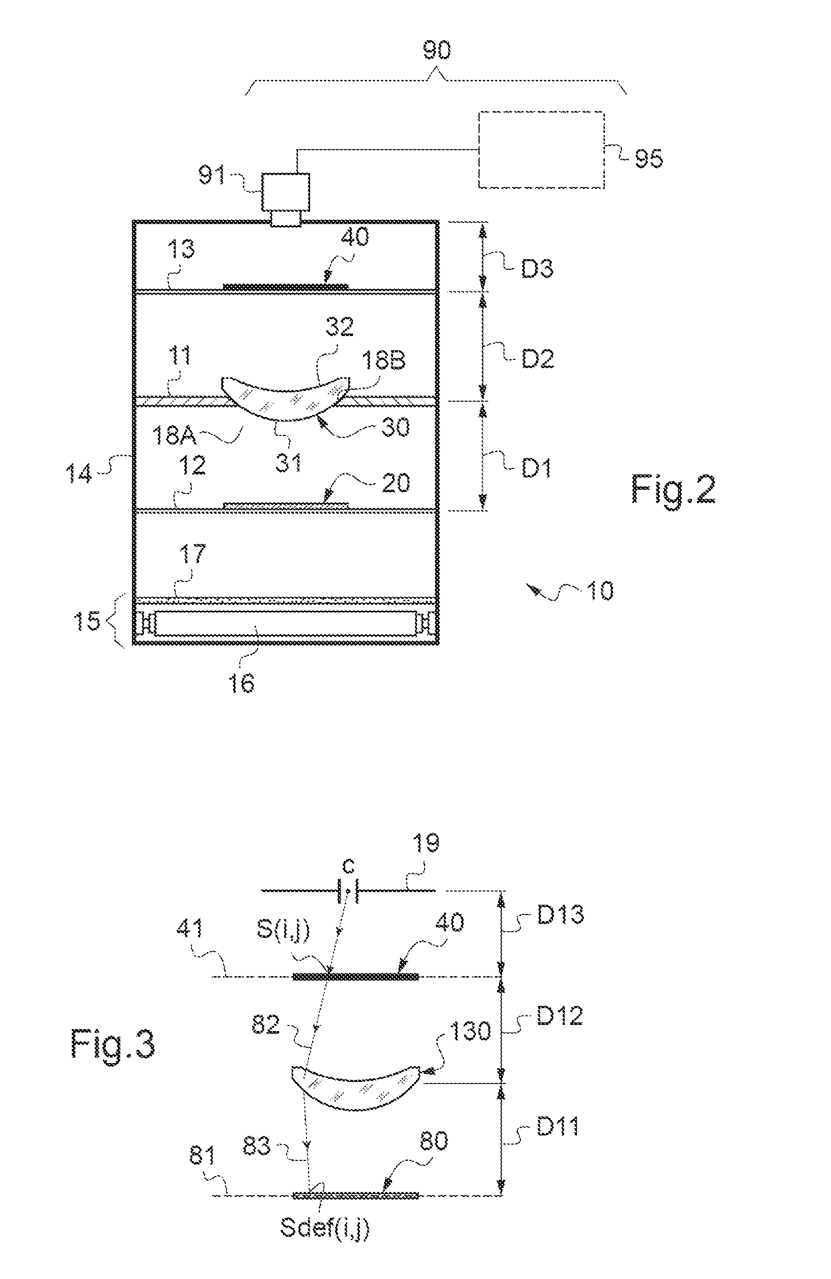
[0054]FIG. 2 is an overview of the verifying device according to the invention;

[0055]FIG. 3 is an optical schematic describing the principle of the optical ray tracing calculation allowing an intermediate test pattern to be determined from an undeformed test pattern and a deformed test pattern to be constructed;

[0056]FIG. 4 is a front view of a first example of an undeformed test pattern of square shape comprising a tiling of black and white square features;

[0057]FIG. 5 shows an intermediate test pattern calculated by optical ray tracing through an expected ophthalmic lens from the undeformed test pattern in FIG. 4;

[0058]FIG. 6 shows a deformed test pattern determined from the intermediate test pattern shown in FIG. 5;

[0059]FIG. 7 shows the test test pattern obtained by superposing the undeformed test pattern in FIG. 4 and the image test pattern that is the image of the deformed test pattern in FIG. 6 through a verified ophthalmic lens;

[0060]FIG. 8 shows a reference test pattern to ...

second embodiment

[0061]FIG. 9 is an overview of a verifying device according to the invention, comprising a storage unit delivering an undeformed test pattern and electronic processing means comprising a local processing unit and a remote processing unit;

third embodiment

[0062]FIG. 10 is an overview of a verifying device according to the invention, in which the deformed test pattern originates from a digital display device;


PUM


Abstract

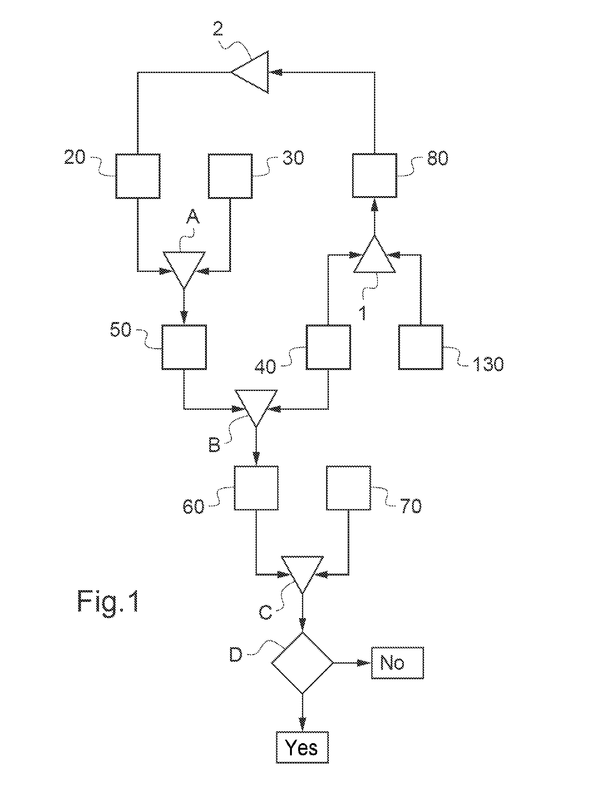
A method for checking the compliance of a checked optical characteristic of a checked ophthalmic lens (30) relative to an expected optical characteristic, from a non-deformed pattern (40) and a deformed pattern (20) each having a non-uniform contrast, the method includes the steps of: a) determining (A) an image pattern (50), which is the image of the deformed pattern through the checked ophthalmic lens, in predefined optical conditions, b) combining (B) the image pattern with the non-deformed pattern to form a test pattern (60), c) comparing (C) the test pattern with at least one reference pattern (70), and d) deducing (D) the compliance of the checked optical characteristic with the expected optical characteristic on the basis of the preceding comparison. A device for implementing such a checking method is also described.

Description

TECHNICAL FIELD OF THE INVENTION[0001]The present invention relates to a method for verifying the conformity of an optical characteristic of a corrective ophthalmic lens to an expected optical characteristic.[0002]It also relates to a device for verifying the conformity of an optical characteristic of an ophthalmic lens to an expected optical characteristic.PRIOR ART[0003]It is important for an optician who receives an ophthalmic lens to be able to verify, rapidly and simply, that all of the optical characteristics of an ordered ophthalmic lens indeed correspond to the expected optical characteristics, especially depending on the prescription of the corresponding wearer.[0004]This is all the more true since ophthalmic lenses have optical characteristics that are increasingly complex due to the development of ophthalmic lenses of personalized design.[0005]For this reason, it is known to measure the frontal power of an ophthalmic lens by means of a manual lensmeter. Nevertheless, this...

Claims


Application Information

Patent Timeline
IPC IPC(8): G01M11/02
CPCG01M11/0285G01M11/0214G01M11/0264G02C13/003
Inventor ALLIONE, PASCAL
Owner ESSILOR INT CIE GEN DOPTIQUE
Learn More