Reverse shoulder systems and methods

Active Publication Date: 2015-10-29
HOWMEDICA OSTEONICS CORP
View PDF2 Cites 43 Cited by
  • Summary
  • Abstract
  • Description
  • Claims
  • Application Information

AI Technical Summary

Benefits of technology

[0009]There is a need for new shoulder prosthesis systems that can provide more flexibility and better adaptability to patient anatomies while maximizing revision options. When implanting reverse shoulder systems it is desirabl

Problems solved by technology

Some reverse shoulder systems have limitations in connection with the fixation of the glenoid component.
The threaded post provides fixation to the bone of the scapula, but provides little to no flexibility of the final positioning of peripheral features of the baseplate, such as screw or mount holes

Method used


Image

  • Reverse shoulder systems and methods
  • Reverse shoulder systems and methods
  • Reverse shoulder systems and methods

Examples


Example

[0045]While the present description sets forth specific details of various embodiments, it will be appreciated that the description is illustrative only and should not be construed in any way as limiting. Furthermore, various applications of such embodiments and modifications thereto, which may occur to those who are skilled in the art, are also encompassed by the general concepts described herein. Each and every feature described herein, and each and every combination of two or more of such features, is included within the scope of the present invention provided that the features included in such a combination are not mutually inconsistent.

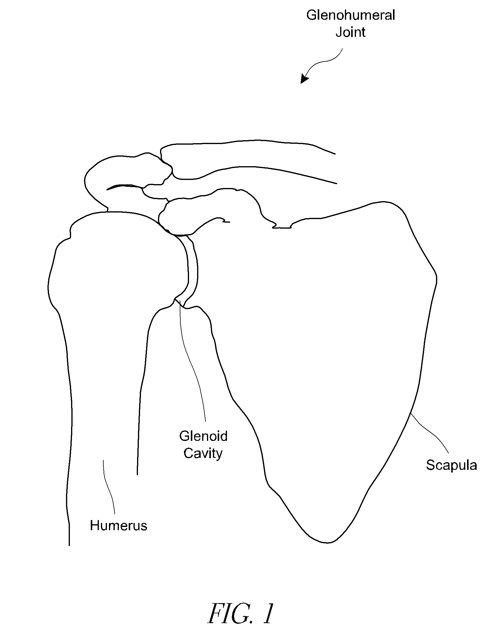
[0046]FIG. 1 depicts the human shoulder. The glenoid cavity is a portion of the shoulder that is located on the scapula. The glenoid cavity articulates with the head of the humerus to permit motion of the glenohumeral joint. Total shoulder arthroplasty replaces the glenohumeral joint with prosthetic articular surfaces that replicate the naturally...


PUM


Abstract

Reversed glenoid implants, and related kits and methods, are described that include an anchor member having a proximal head and a baseplate having a distal end with a first aperture sized to accept the proximal head of the anchor member. The proximal head is inserted along an un-threaded length thereof from the distal end into the first aperture, and the anchor member is restrained against axial translation with respect to the baseplate but is permitted to rotate with respect to the baseplate.

Description

INCORPORATION BY REFERENCE TO ANY PRIORITY APPLICATIONS[0001]Any and all applications for which a foreign or domestic priority claim is identified in the Application Data Sheet as filed with the present application are hereby incorporated by reference under 37 C.F.R. §1.57.BACKGROUND OF THE INVENTION[0002]1. Field of the Invention[0003]The systems and methods described herein are directed to orthopedic implants, for example to reverse shoulder replacement systems and methods for implantation.[0004]2. Description of the Related Art[0005]Shoulder replacement surgery involves placing a motion providing device at the glenohumeral joint, i.e., the joint interface between the scapula and the proximal humerus of the arm. See FIG. 1. Reverse shoulder replacement reverses the curvature of the natural glenoid cavity and the proximal head of the humerus. That is, a convex surface of a glenoid component is positioned on the scapula and a concave surface of a humeral component is positioned on t...

Claims


Application Information

Patent Timeline
IPC IPC(8): A61F2/40
CPCA61F2/4081A61F2002/4085A61F2002/30405A61F2002/30013A61F2/30749A61B17/8033A61B17/8052A61B17/86A61F2002/30332A61F2002/30367A61F2002/305A61F2002/30507A61F2002/30538A61F2002/30571A61F2002/30607A61F2002/30774A61F2002/30787A61F2002/3085A61F2002/30495A61F2002/30011
Inventor GARGAC, SHAWN M.HODOREK, BRIAN C.KUESTER, WILLIAM MATTHEWMUTCHLER, AUSTIN WYATT
Owner HOWMEDICA OSTEONICS CORP
Why Eureka
Try Eureka