
Apparatus and method for non-destructive testing of concrete

a non-destructive testing and apparatus technology, applied in the direction of instruments, heat measurement, specific gravity measurement, etc., can solve the problems of difficult to effectively obtain an echo signal, inability to use adjacent sides,

Inactive Publication Date: 2015-10-29
NLA DIAGNOSTICS
View PDF6 Cites 22 Cited by
  • Summary
  • Abstract
  • Description
  • Claims
  • Application Information

AI Technical Summary

Benefits of technology

The present invention relates to a method and device for determining characteristics of a concrete sample. The method involves using a broadband transducer to establish a standing wave in the concrete sample and detect it using a narrowband transducer at a different position. The resonant frequency of the standing wave is determined, and the velocity of a second mechanical wave is determined based on the resonant frequency and the velocity of the second mechanical wave. The depth of a characteristic of the concrete sample can then be determined based on the resonant frequency, the velocity of the second mechanical wave, and the position of the narrowband transducer. The device includes a frame and a plurality of transducers secured to the frame at predetermined positions with respect to each other. The transducers can be actuated to impart mechanical waves in the concrete sample and detect the waves using other transducers. The characteristics of the concrete sample can then be determined based on the detected waves.

Problems solved by technology

Typically, the use of adjacent sides is not possible because the amplitude of the pressure and the torsion waves are difficult to determine.
Ultrasound is highly attenuated in concrete, and for increasing thicknesses, it may therefore be difficult to effectively obtain an echo signal.

Method used


Image

  • Apparatus and method for non-destructive testing of concrete
  • Apparatus and method for non-destructive testing of concrete
  • Apparatus and method for non-destructive testing of concrete

Examples


Embodiment Construction

[0078]Reference will now be made in detail to presently preferred embodiments of the invention, one or more examples of which are illustrated in the accompanying drawings. Each example is provided by way of explanation of the invention, not limitation of the invention. In fact, it will be apparent to those skilled in the art that modifications and variations can be made in the present invention without departing from the scope and spirit thereof. For instance, features illustrated or described as part of one embodiment may be used on another embodiment to yield a still further embodiment. Thus, it is intended that the present invention covers such modifications and variations as come within the scope of the present disclosure.

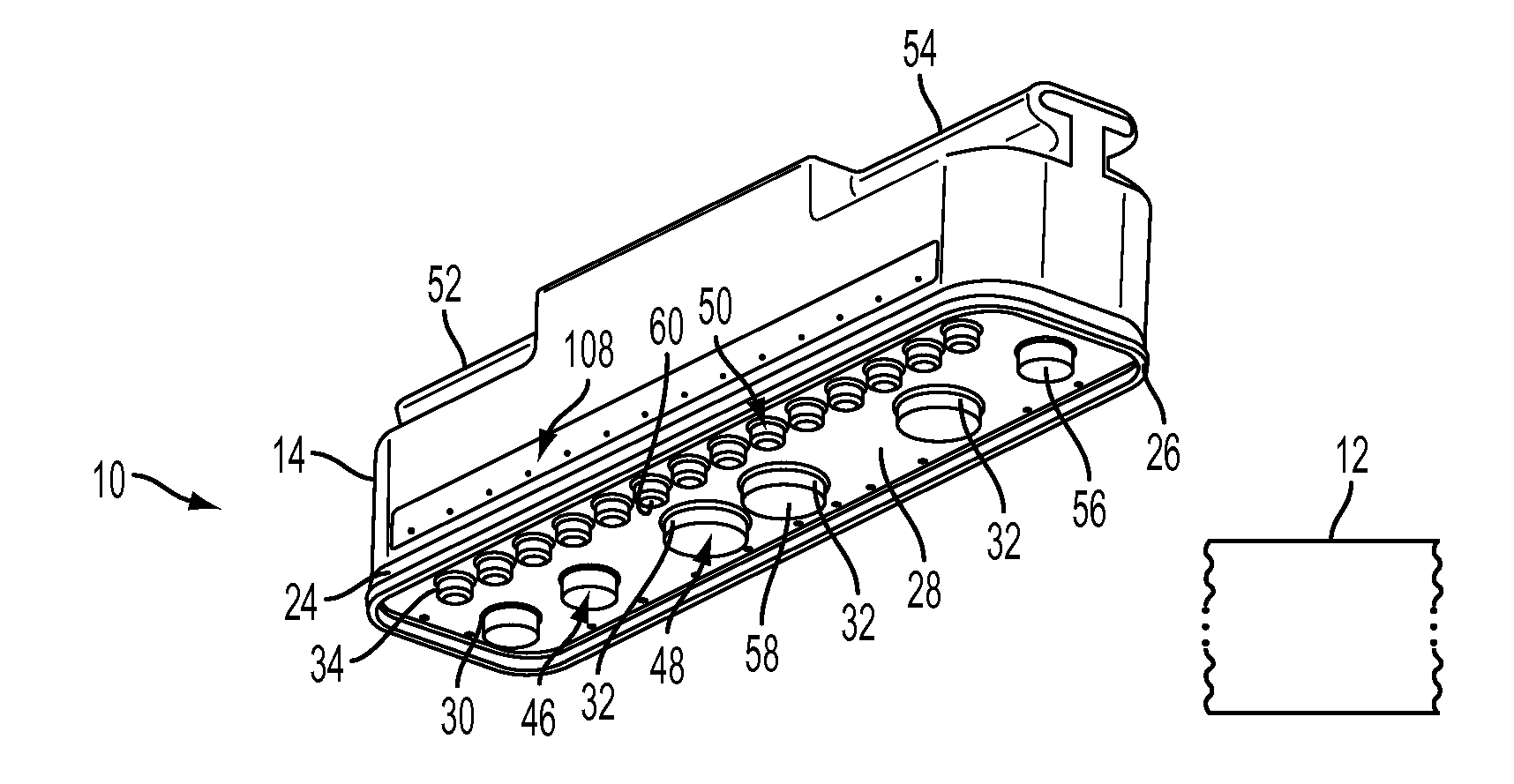
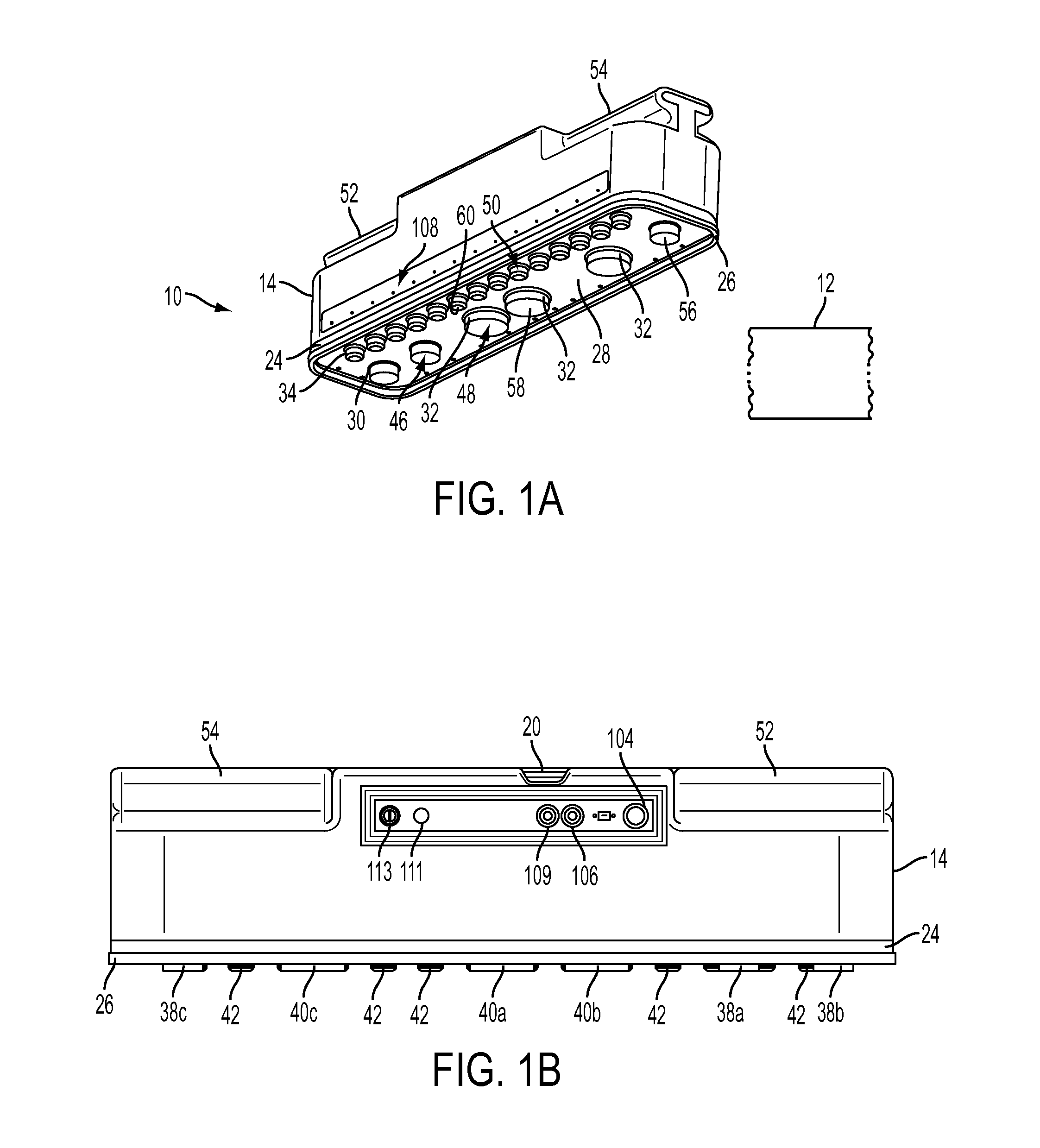
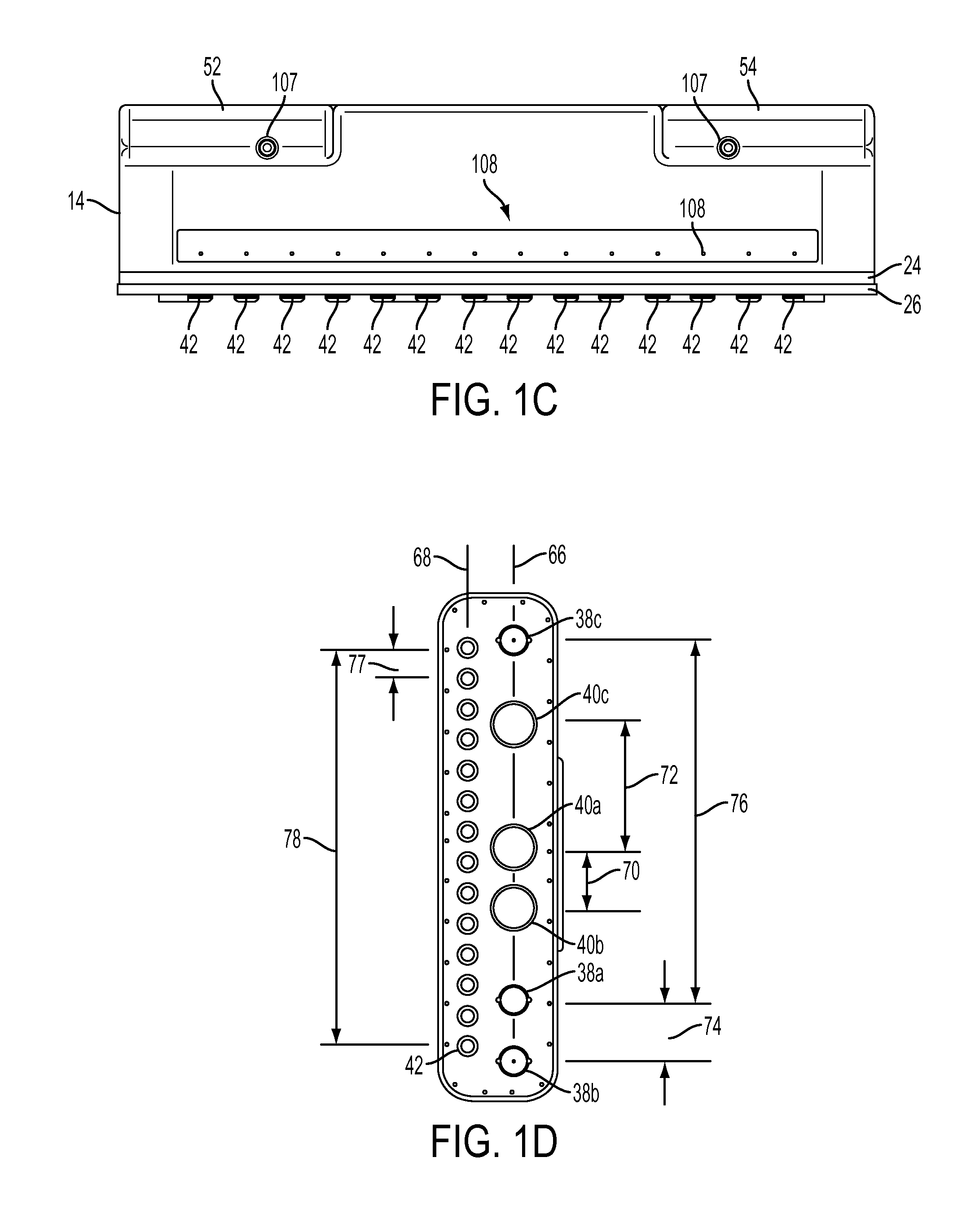
[0079]Referring to FIGS. 1A-1E and 2, a hand held device 10 for determining characteristics of a concrete sample 12, for example a wall, includes a housing 14 that encloses a transducer array unit assembly 16 and a control device comprised of a data acquisition...


PUM

PropertyMeasurementUnit
compressive strengthaaaaaaaaaa
frequencyaaaaaaaaaa
resonant frequencyaaaaaaaaaa

Abstract

A device and method for determining characteristics of a concrete sample includes the use of multiple transducers at pre-determined positions with respect to each other. The transducers are coupled to the concrete surface so that they can impart and / or receive mechanical waves from the sample. Mechanical waves may be imparted to the sample by one or more transducers or by an impact hammer. A control device receives the output from receiving transducers and analyzes data there from to determine a desired characteristic of the sample.

Description

[0001]The present application claims priority to U.S. provisional patent application Ser. No. 61 / 986,029, filed Apr. 29, 2014, entitled APPARATUS AND METHOD FOR NON-DESTRUCTIVE TESTING OF CONCRETE, the entire disclosure of which is hereby incorporated by reference herein.[0002]This invention was made with government support under contract number W911NF-14-C-0010 awarded by the Department of Defense. The government has certain rights in the invention.[0003]A portion of the disclosure of this patent document contains material which is subject to copyright protection. The copyright owner has no objection to the facsimile reproduction by any-one of the patent document or the patent disclosure, as it appears in the Patent and Trademark Office patent file or records, but otherwise reserves all copyright whatsoever.BACKGROUND[0004]The present invention relates to the use of mechanical waves in the non-destructive testing of concrete.[0005]Methods and devices are known that utilize the prop...

Claims


Application Information

Patent Timeline
Patent Type & Authority Applications(United States)
IPC IPC(8): G01N33/38G01N29/07
CPCG01N33/383G01N29/07G01N2291/0422G01N2291/0232G01N2291/011G01N29/348G01N2291/02827
Inventor BELLOTTI, ALDOSTRAYHORN, IV, RALPH N.
Owner NLA DIAGNOSTICS
Learn More