Irradiation device for irradiating plants

a technology of irradiation device and plant, which is applied in the field of irradiation device for irradiation plant, can solve the problems of shortening the service life of the components complicated production of the irradiation device, and high power output,

Inactive Publication Date: 2015-11-05
HERAEUS NOBLELIGHT GMBH
View PDF3 Cites 20 Cited by
  • Summary
  • Abstract
  • Description
  • Claims
  • Application Information

AI Technical Summary

Benefits of technology

[0014]The invention is therefore based on the object of providing an irradiation device for irradiating plants, which has a long service life and ensures, in addition to irradiating plants with ultraviolet and / or visible radiation, a uniform irradiation of the plants with infrared radiation, without unnecessarily negatively affecting the irradiation with ultraviolet and / or visible radiation and, in addition, requires a small number of infrared emitters in relation to the culture area.

Problems solved by technology

With a lateral arrangement of the infrared emitters in relation to the cultivation surface, a large number of emitters is required, which must have a low power output in order not to damage the plants in the outer area of the culture area due to excessive heating Infrared emitters, however, typically have a high power output; emitters of low power output are complicated to make and have only a limited service life.
In addition, the lateral arrangement of the infrared emitters also contributes to irradiation and heating of the other components provided in the irradiation device, for example the electrical cables and mounting elements for the radiation sources, and also the radiation sources provided in the irradiation device, whereby the service lives of these components are shortened due to the irradiation.
A lateral arrangement of the infrared emitters is therefore associated with high operating costs.

Method used


Image

  • Irradiation device for irradiating plants
  • Irradiation device for irradiating plants
  • Irradiation device for irradiating plants

Examples


Embodiment Construction

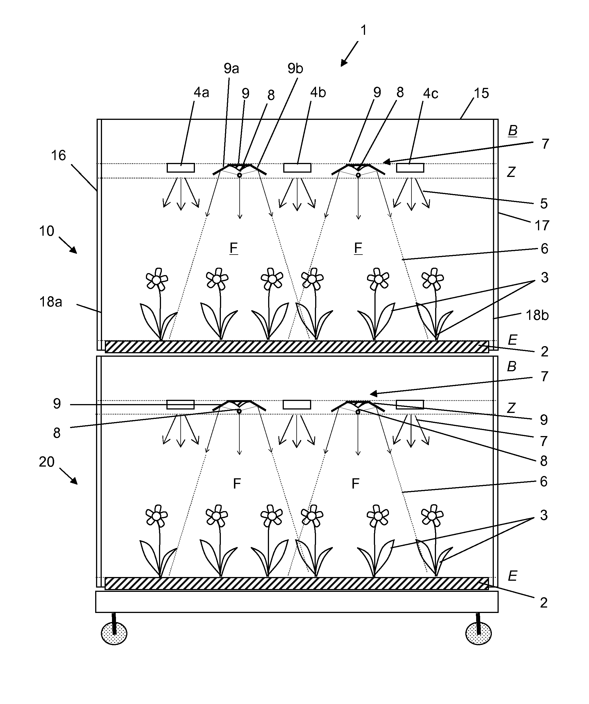
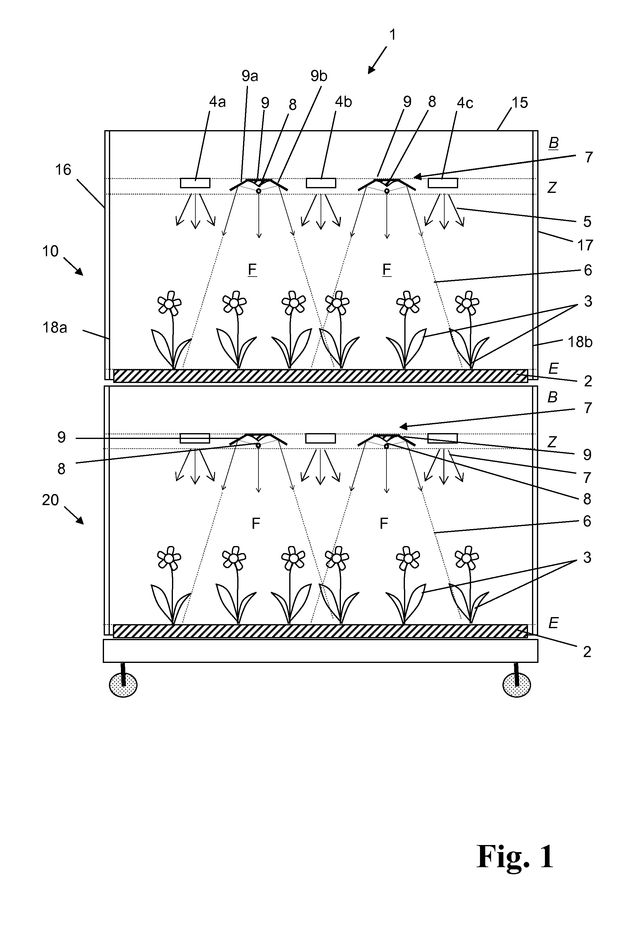
[0090]FIG. 1 shows an irradiation device for irradiating plants, which is designated overall with reference number 1. The irradiation device 1 is provided for tiered crop growing and comprises a housing 15 having five plant modules (tiers) arranged one above the other for the cultivation of plants, of which only two plant modules 10, 20 are shown in FIG. 1 for the purpose of simplification. The plant modules that are not shown have identical constructions to the plant modules 10, 20. A reflector film 18a, 18b is applied on both side walls 16, 17 of the housing.

[0091]The plant modules 10, 20 comprise a carrier element 2 and an installation space B arranged above the carrier element 2 and having electrical cables and mounting elements, as well as the emitter zone Z arranged under the installation space. The carrier element 2 is filled with dirt and planted with several plants 3. The surface of the planted carrier element defines a culture plane E. The emitter zone Z is located above t...


PUM


Abstract

A device is provided which ensures uniform irradiation of plants with infrared radiation along with ultraviolet and / or visible radiation and requires a small number of infrared emitters relative to the cultivation area. The infrared emitters are designed for temperatures of 800° C. to 1800° C. Each has a cylindrical emitter tube having a length of 50 mm to 500 mm. The emitter tubes extend parallel to one another in an emitter zone located above the culture plane. The infrared emitter occupation density relative to the area of the culture plane is between 0.2 m−2 and 1.0 m−2. Irradiation regions of adjacent infrared emitters on the culture plane overlap such that average irradiance on the culture plane is between 10 watt / m2 and 100 watt / m2 with a variation range of a maximum of 50%. A reflector facing a structural space is assigned to a top side of the emitter tube.

Description

CROSS-REFERENCE TO RELATED APPLICATIONS[0001]This application is a Section 371 of International Application No. PCT / EP2013 / 075754, filed Dec. 6, 2013, which was published in the German language on Jun. 19, 2014, under International Publication No. WO 2014 / 090693 A1 and the disclosure of which is incorporated herein by reference.BACKGROUND OF THE INVENTION[0002]The present invention relates to an irradiation device for irradiating plants, comprising a carrier element defining a culture plane E for cultivating the plants, multiple irradiation sources for irradiating the plants with visible and / or ultraviolet radiation, and multiple infrared emitters for irradiating the plants with infrared radiation.[0003]The present invention further relates to an emitter module for irradiating plants with infrared radiation for use in an irradiation device.[0004]For the breeding and cultivation of plants, for example in greenhouses and in tiered crop growing, artificial light sources are used. The e...

Claims


Application Information

Patent Timeline
Patent Type & Authority Applications(United States)
IPC IPC(8): A01G7/04
CPCA01G7/045A01G9/249Y02P60/14
Inventor WEISS, OLIVERLINOW, SVEN
Owner HERAEUS NOBLELIGHT GMBH
Why Eureka
Try Eureka