Eureka AIR delivers breakthrough ideas for toughest innovation challenges, trusted by R&D personnel around the world.

Monitoring method for a continuous casting mould including building up a database

a monitoring method and continuous casting technology, applied in the direction of mould control devices, manufacturing tools,foundry moulding apparatus, etc., can solve the problems of exceptionally time-consuming and limited application of the approach

Inactive Publication Date: 2015-11-05
PRIMETALS TECH AUSTRIA GMBH
View PDF1 Cites 31 Cited by
  • Summary
  • Abstract
  • Description
  • Claims
  • Application Information

AI Technical Summary

Benefits of technology

The present invention provides a tool for categorizing the values determined into permissible or impermissible, or into good or bad. This helps the operator to easily identify and handle abnormal or abnormal-like values. The invention also aims to automatically fill the database with orderly data records and to draw on those already present in the database for assessing the current operating parameters. The computer program incorporates machine code that can be directly executed by the monitoring equipment for a continuous casting mold. The execution of this code results in the monitoring equipment carrying out a monitoring method in accordance with the invention. Overall, the invention simplifies and streamlines the monitoring process, making it more efficient and effective.

Problems solved by technology

However, this approach is only applicable to a restricted extent if the metal strand being cast has a new chemical composition—for example a new type of steel—if a different casting powder is being used or if over a period of time a large number of metal strands are cast which differ in their chemical composition.
However, this approach is exceptionally time-consuming, and apart from that is liable to error.

Method used


Image

  • Monitoring method for a continuous casting mould including building up a database
  • Monitoring method for a continuous casting mould including building up a database
  • Monitoring method for a continuous casting mould including building up a database

Examples


Embodiment Construction

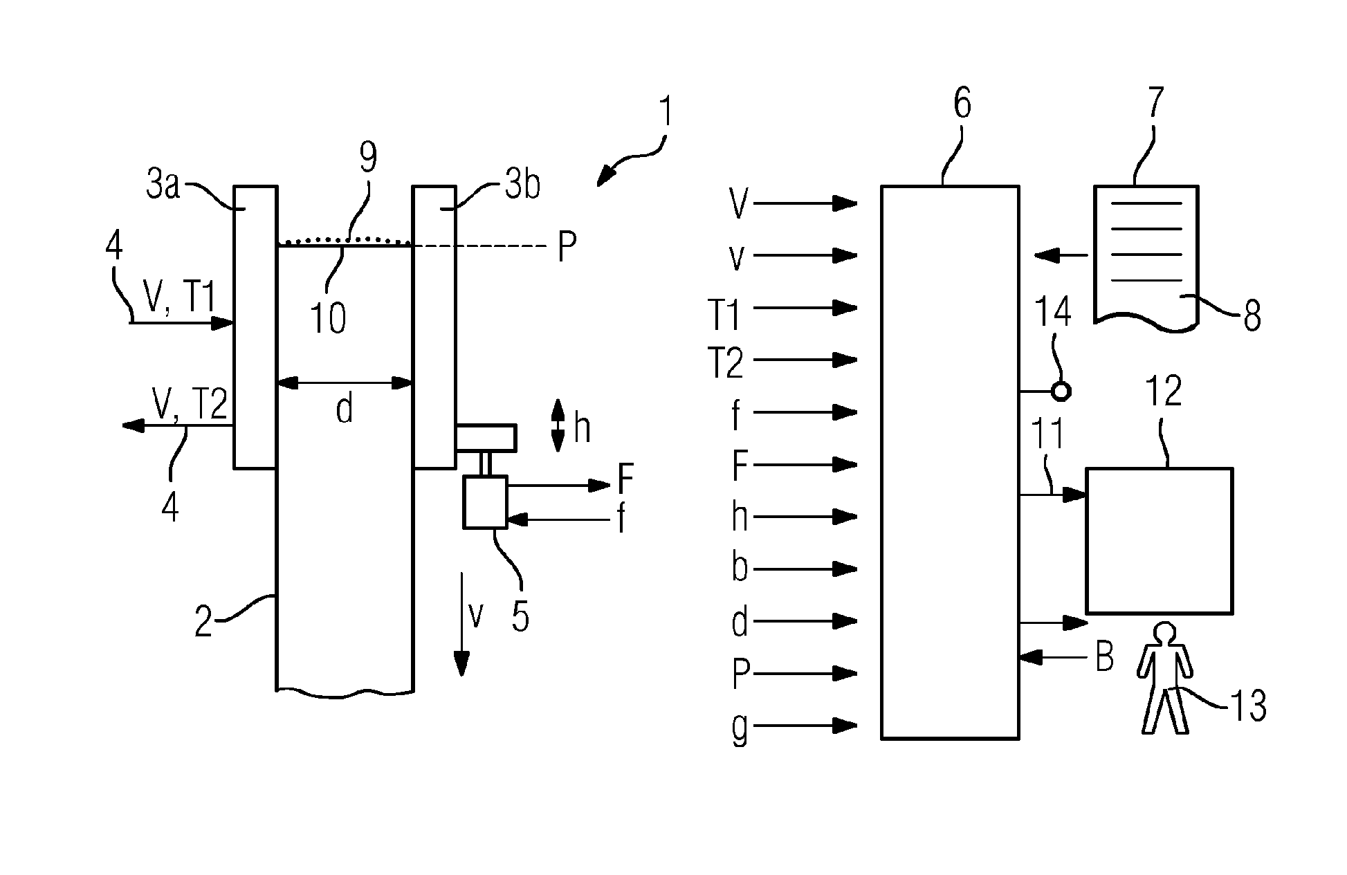
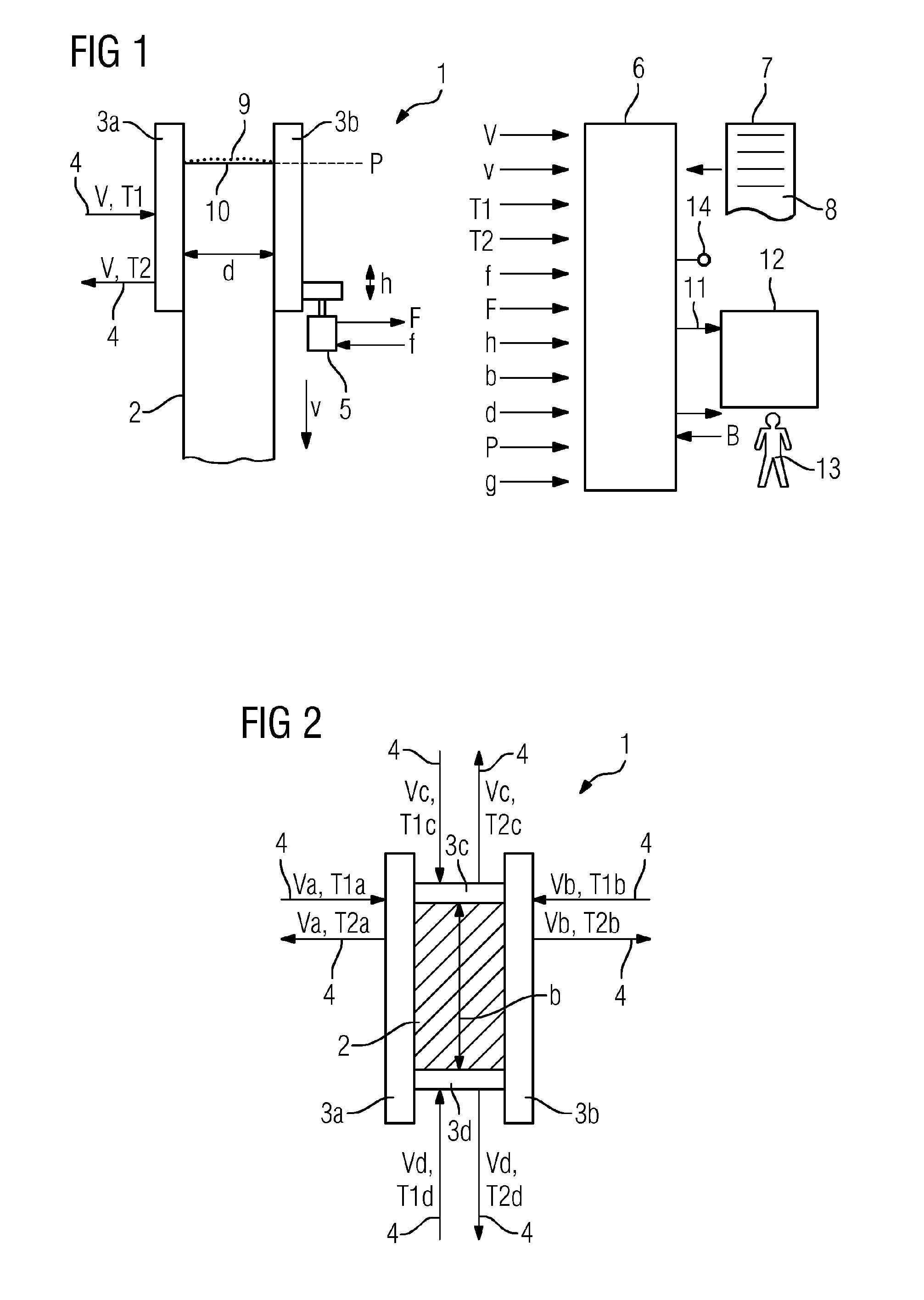
[0056]As shown in FIGS. 1 and 2, a metal strand 2 is cast using a continuous casting mold 1. The metal strand 2 can, in particular, consist of steel. The metal strand 2 can, as shown in the illustrations in FIGS. 1 and 2, be strip-shaped in form. In this case, the continuous casting mold 1 has several sidewalls 3a to 3d. Furthermore, in the case of a strip-shaped metal strand 2, two of the sidewalls 3a to 3d are each constructed as wide sides 3a, 3b and two each as narrow sides 3c, 3d. The distances from each other of the sidewalls, 3a to 3d, which lie opposite each other define the format of the metal strand 2 which is cast, in particular its thickness d and its width b. Alternatively however, other formats can also be cast, in particular rod cross-sections. In this case, the continuous casting mold 1 has only a single sidewall.

[0057]The continuous casting mold 1 is cooled by means of a liquid coolant 4—generally water. Per unit of time (for example, per second), a volume flow V of...


PUM

PropertyMeasurementUnit
timeaaaaaaaaaa
cycle timeaaaaaaaaaa
repetition timeaaaaaaaaaa

Abstract

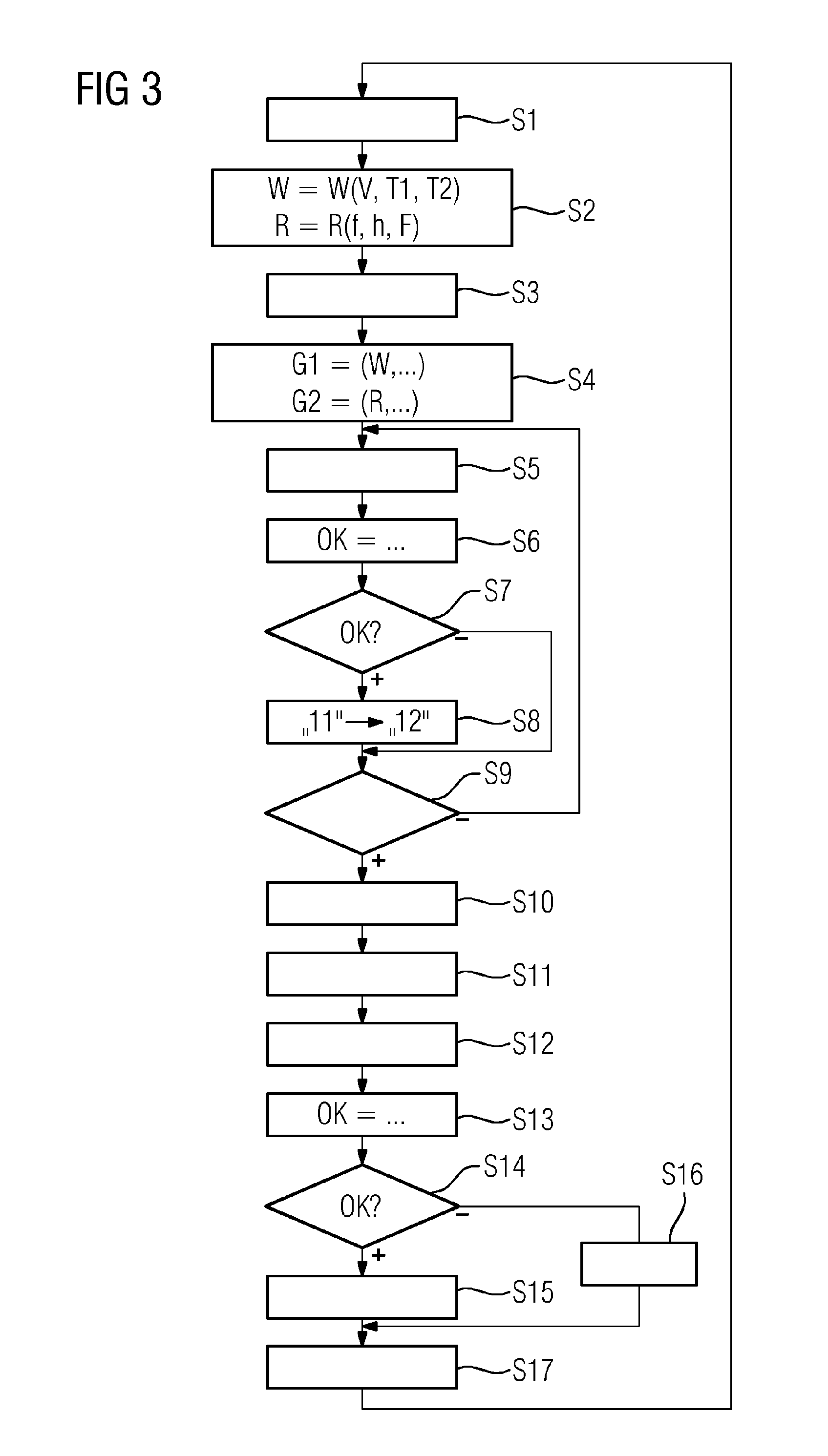
A monitoring device (6) records variables that are characteristic of operating parameters of a continuous casting mold (1) for casting a metal strand (2). The monitoring device (6) records at least some of the characteristic variables by independently performing measurements during the casting of the metal strand (2). The monitoring device (6) forms groups (G1, G2) of operating parameters and independently tests whether the operating parameters of the respective group (G1, G2) satisfy a respective predetermined stability criterion. The monitoring device (6) accepts the operating parameters into a database (12). The monitoring device (6) determines those data records (11) contained in the database (12) that coincide in their input variables with the basic operating parameters and determines admissible operating parameter ranges for supplementary operating parameters. The monitoring device (6) independently tests whether the supplementary operating parameters lie within the admissible operating parameter ranges.

Description

CROSS-REFERENCE TO RELATED APPLICATIONS[0001]The present application is a 35 U.S.C. §§371 national phase conversion of PCT / EP2013 / 072544, filed Oct. 29, 2013, which claims priority of German Patent Application No. 10 2012 224 132.9, filed Dec. 21, 2012, the contents of which are incorporated by reference herein. The PCT International Application was published in the German language.TECHNICAL BACKGROUND[0002]The present invention relates to a method of monitoring for a continuous casting mold for casting a metal strand,[0003]wherein monitoring equipment detects quantities,[0004]wherein the monitoring equipment automatically detects metrologically at least some of the quantities during the casting of the metal strand[0005]wherein the monitoring equipment uses the quantities detected to determine operating parameters of the continuous casting mold.[0006]A monitoring method of this type is known, for example in the form of SIMETALL MOLD EXPERT from Siemens VAI Metals Technologies GmbH, ...

Claims


Application Information

Patent Timeline
Patent Type & Authority Applications(United States)
IPC IPC(8): B22D11/16B22D11/114
CPCB22D11/114B22D11/16B22D11/20B22D11/22B22D11/165B22D11/166B22D11/122
Inventor LANG, OLIVERORTNER, CHRISTIANSCHUSTER, MARTIN
Owner PRIMETALS TECH AUSTRIA GMBH
Why Eureka
Eureka Blog
Learn More