Roofing shingle system and shingles for use therein

a technology for roof shingle and shingles, which is applied in the field of improved roofing shingles, can solve the problems of chain reaction lifting up adjacent tabs, affecting the appearance of the shingle, and the two-layer roofing shingles disclosed in u.s. patent no. 7,805,905 are susceptible to wind failure, and achieve superior weather resistance and aesthetics, and reduce the risk of wind failur

Active Publication Date: 2015-11-05
BMIC LLC
View PDF2 Cites 21 Cited by
  • Summary
  • Abstract
  • Description
  • Claims
  • Application Information

AI Technical Summary

Benefits of technology

[0021]One embodiment of this invention pertains to a new two-layer asphalt containing roofing shingle having superior weather resistance and an aesthetic appearance, which simulates a variable thickness slate, tile or wood shake roofing surface, and which further employs a novel backer strip to reduce the risk of wind failure.
[0022]In accordance with one embodiment of the present invention, a roofing system is provided having a multiplicity of courses of two-layer roofing shingles, wherein each shingle has a posterior layer (also known as a backer strip) and an anterior layer (also known as a facer), wherein the anterior layer of each shingle has a plurality of tabs spaced apart by a plurality of openings and the posterior layer has a plurality of “partial slots” (defined herein as openings cut into the posterior layer that do not extend to any edge of the buttlap), wherein the partial slots separate the posterior “simulated tabs” (defined herein as regions of the buttlap of a shingle or shingle layer that resemble traditional shingle or shingle layer tabs, but are not completely separated from adjacent similar regions at any edge of the buttlap), wherein the simulated tabs are connected to at least one adjacent simulated tab by a “connecting segment” (defined herein as a portion of shingle or shingle layer material disposed between simulated tabs), and wherein the connecting segment may be located at or near the buttlap edge of the shingle or shingle layer. The connecting segments provide rigidity to single-thickness simulated tabs compared to traditional single-thickness tabs of prior art shingles, while the partial slots provide the visual appearance of discrete tabs that help convey the appearance of bulk. The relatively random pattern of the anterior tabs and anterior openings along with the simulated appearance of discrete posterior tabs (achieved by partial slots and simulated tabs) create the illusion of thickness that makes the roofing shingles appear like more expensive roofing materials such as tile, slate, or wood shakes.
[0025]Applicants have addressed this problem with the invention disclosed and claimed herein. In a preferred embodiment, the partial slots (and optionally the connecting segment, when modified as described below) operate to simulate the appearance of traditional, discrete posterior tabs, while the connecting segment provides rigidity to the single-thickness simulated tabs protecting the simulated tabs from lifting up under mild wind conditions prior to the shingles fully sealing. Not being bound by any particular theory, increased rigidity may be imparted to a single-thickness simulated tab because the simulated tab is connected directly or indirectly to a double-thickness (or multi-layer) simulated tab that has increased rigidity and weight due to increased thickness. Alternatively, a simulated tab may have increased rigidity by virtue of being connected to at least one other simulated tab regardless of the thickness of the simulated tabs on the shingle, i.e., the present invention will provide rigidity and increased protection from wind failure even if the entire shingle is only one layer thick. It will be appreciated that the present invention can be used to impart increased structural rigidity, while still maintaining the aesthetic appearance of discrete tabs without the increased weight of additional material that may otherwise be needed to impart such increased structural rigidity, e.g., the basis weight of a single-layer simulated tab compared to the basis weight of a multi-layered discrete tab.
[0059]The shingles of the invention are improvements of roofing shingle materials known in the art, wherein the improvements are providing roofing shingles having simulated tabs that are connected to at least one adjacent simulated tab by a connecting segment, which simulate the appearance of traditional, discrete tabs and having improved weather performance over the prior art, especially with respect to resisting wind failure.

Problems solved by technology

The two-layer roofing shingles disclosed in U.S. Pat. No. 7,805,905 are susceptible to wind failure when the shingles are installed in cold weather.
When this occurs, dust and other contaminants may land underneath the affected tab, causing it to never fully seal.
This affected tab is then susceptible to lifting up due to wind, which may cause a chain reaction lifting up adjacent tabs and eventually the entire shingle.

Method used


Image

  • Roofing shingle system and shingles for use therein
  • Roofing shingle system and shingles for use therein
  • Roofing shingle system and shingles for use therein

Examples


Embodiment Construction

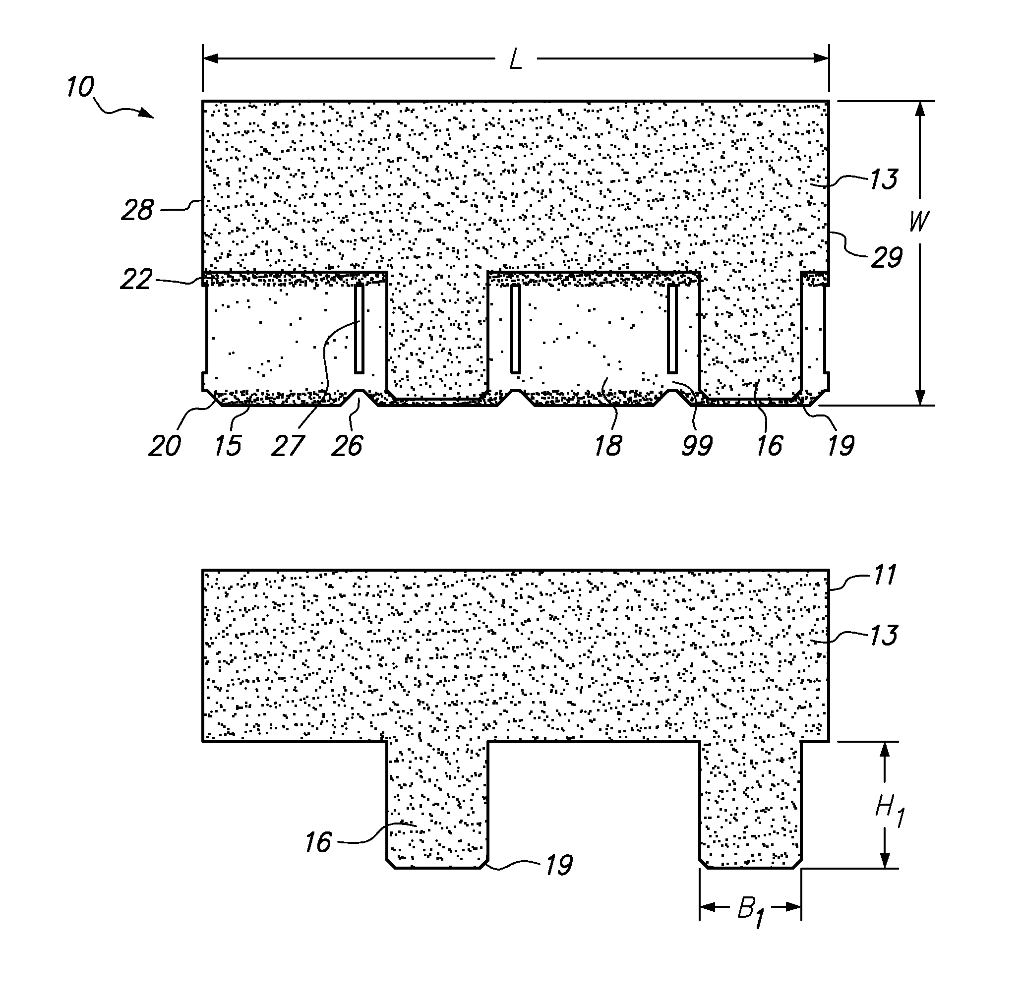
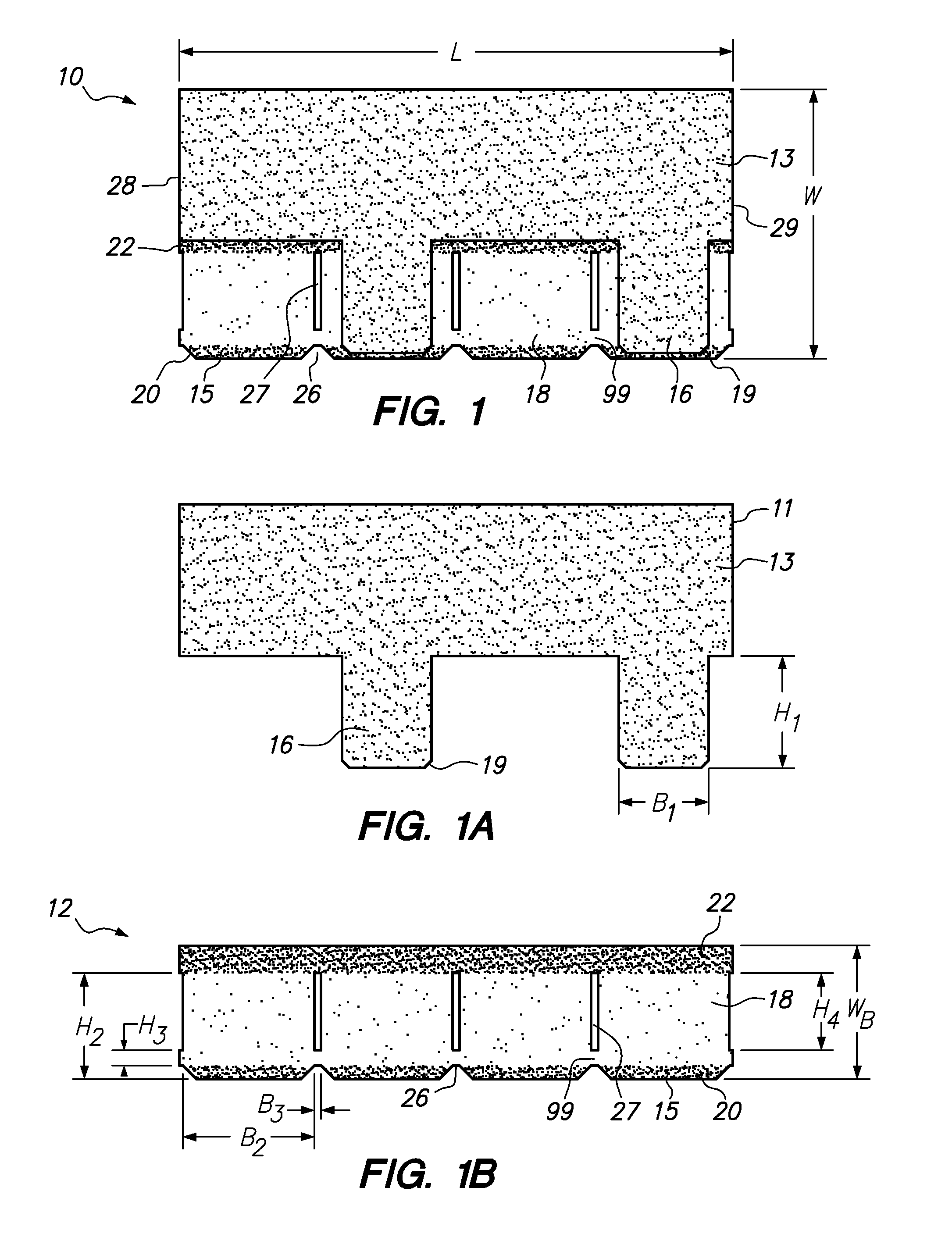
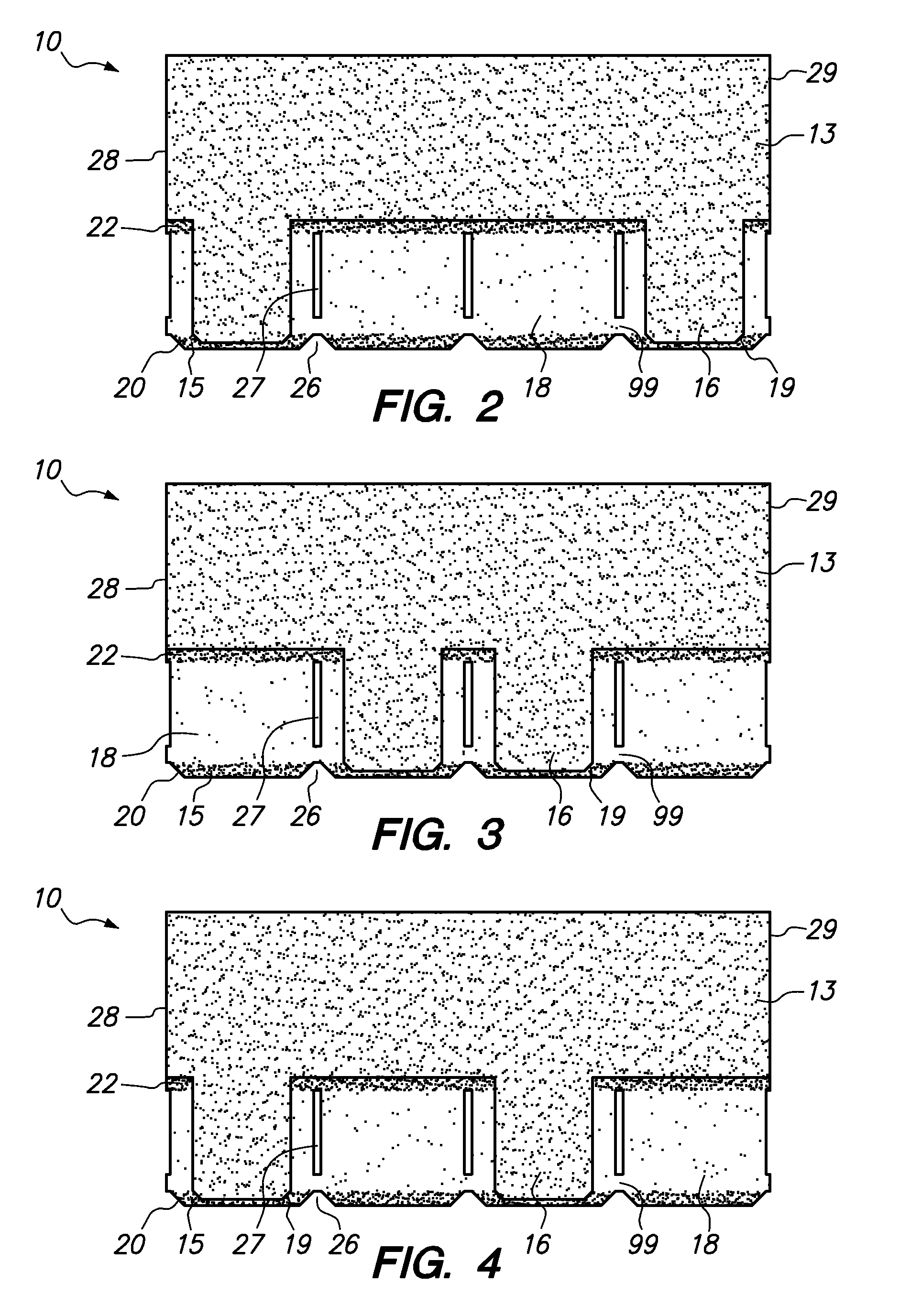
[0072]The preferred embodiments of the present invention and its advantages are best understood by referring to FIGS. 1 through 21, like numerals being used for like and corresponding parts of the various drawings. The different shadings of the individual layers in the drawings are not intended to signify a particular color value or intensity but only to indicate color contrasts between the layers, and each individual layer may be lighter or darker than the shadings indicate; however a color contrast between the layers is optionally employed.

[0073]The first embodiment of the present invention, which relates to two-layer composite roofing shingles having the appearance of variable thickness, will now be described in greater detail by referring to the drawings that accompany the present application.

[0074]Reference is first made to FIGS. 1, 1A, 1B, 2-13, and 14 illustrating top plan views of the inventive two-layer composite shingle having an anterior layer 11 and a posterior layer 12,...


PUM


Abstract

A two-layer laminated roofing shingle is disclosed comprising a posterior layer having an upper portion and a buttlap including a plurality of simulated tabs extending from the posterior upper portion, each simulated tab is connected to at least one adjacent simulated tab by a connecting segment, and an anterior layer having a headlap and a buttlap including one or more anterior tabs extending from the anterior headlap. Also disclosed is a single layer roofing shingle comprising a headlap and a buttlap including a plurality of simulated tabs extending from said headlap, the simulated tabs spaced apart by a plurality of partial slots, and each simulated tab is connected to at least one adjacent simulated tab by a connecting segment. Also disclosed is a roofing system comprising a plurality of courses of the inventive shingles.

Description

RELATED APPLICATIONS[0001]This application is a continuation-in-part of U.S. Non-Provisional application Ser. No. 14 / 266,294, filed on Apr. 30, 2014, entitled “Roofing Shingle System and Shingles for Use Therein,” which is incorporated herein by reference in its entirety for all purposes within this application.FIELD OF THE INVENTION[0002]This invention relates to an improved roofing shingle having the bulk and configuration of more expensive roofing shingles and a roofing system that utilizes the shingles. The inventive roofing shingles have the appearance of thicker shingles and have excellent fire resistance and protection against weather, while retaining the substantially reduced cost of conventional asphalt shingles.BACKGROUND OF THE INVENTION[0003]Roofing products are often divided into three broad groups: shingles, roll roofing, and underlayment. Shingles and roll roofing typically function as outer roof coverings designed to withstand exposure to weather and the elements. Sh...

Claims


Application Information

Patent Timeline
Patent Type & Authority Applications(United States)
IPC IPC(8): E04D1/28E04D1/12
CPCE04D1/28E04D2001/005E04D1/12E04D1/26
Inventor BUZZA, STEPHEN A.
Owner BMIC LLC
Why Eureka
Try Eureka