Submersible transmission fluid pump assembly

a transmission fluid and pump assembly technology, applied in the field of pump assemblies, can solve the problems of large in-process inventories, large number of different/unique parts, and high cost per part, and achieve the effects of minimizing part numbers, maximizing use of common parts, and low volume runs of many parts

Active Publication Date: 2015-11-05
GHSP
View PDF12 Cites 15 Cited by
  • Summary
  • Abstract
  • Description
  • Claims
  • Application Information

AI Technical Summary

Benefits of technology

[0015]An object of the present invention is to provide pump assemblies capable of meeting individually unique constraints on size, shape, control, and performance characteristics, yet doing so without the need for large numbers of different / unique parts, without the need for large in-process inventories, and concurrently while reducing the need for relatively low volume runs of many parts.
[0016]An object of the present invention is to provide a pump assembly capable of meeting performance and special requirements set by vehicle manufacturers, especially for handling automatic transmission fluid and while located in a reservoir of an automatic transmission, while also minimizing part numbers, while maximizing use of common parts on “related but different” pump assemblies, yet while maintaining flexibility of design.

Problems solved by technology

More specifically, each vehicle model tends to have individually unique constraints on size, shape, control, and performance characteristics of its pump assembly.
This can result large numbers of different / unique parts, large in-process inventories, and concurrently in relatively low volume runs of many parts.
This in turn results in higher costs per part, higher costs per assembly, and dramatically increased complexity of assembly.

Method used


Image

  • Submersible transmission fluid pump assembly
  • Submersible transmission fluid pump assembly
  • Submersible transmission fluid pump assembly

Examples


Embodiment Construction

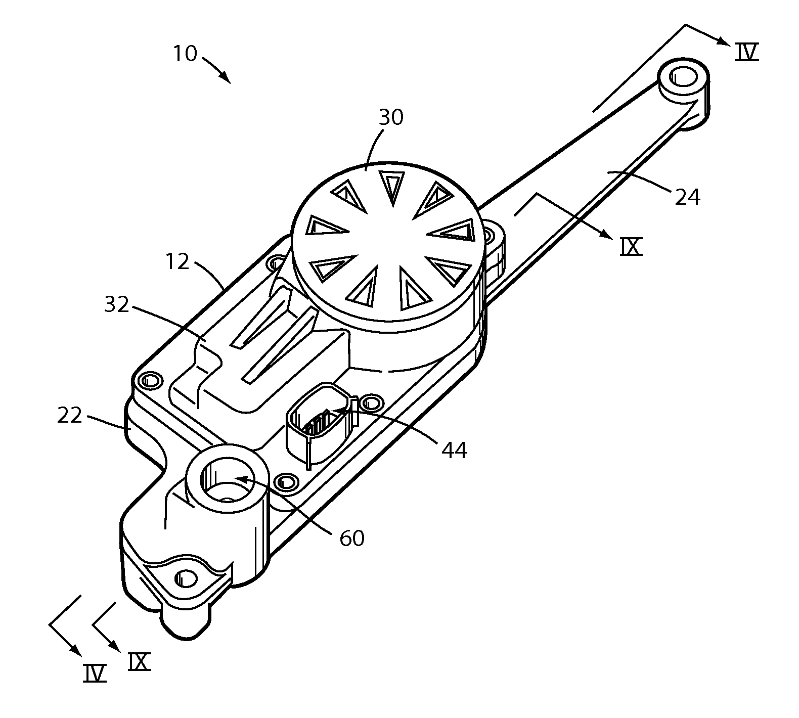
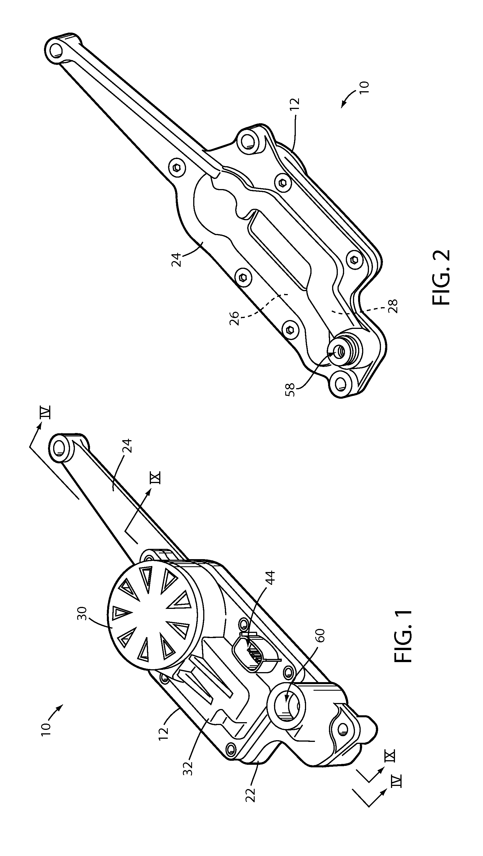
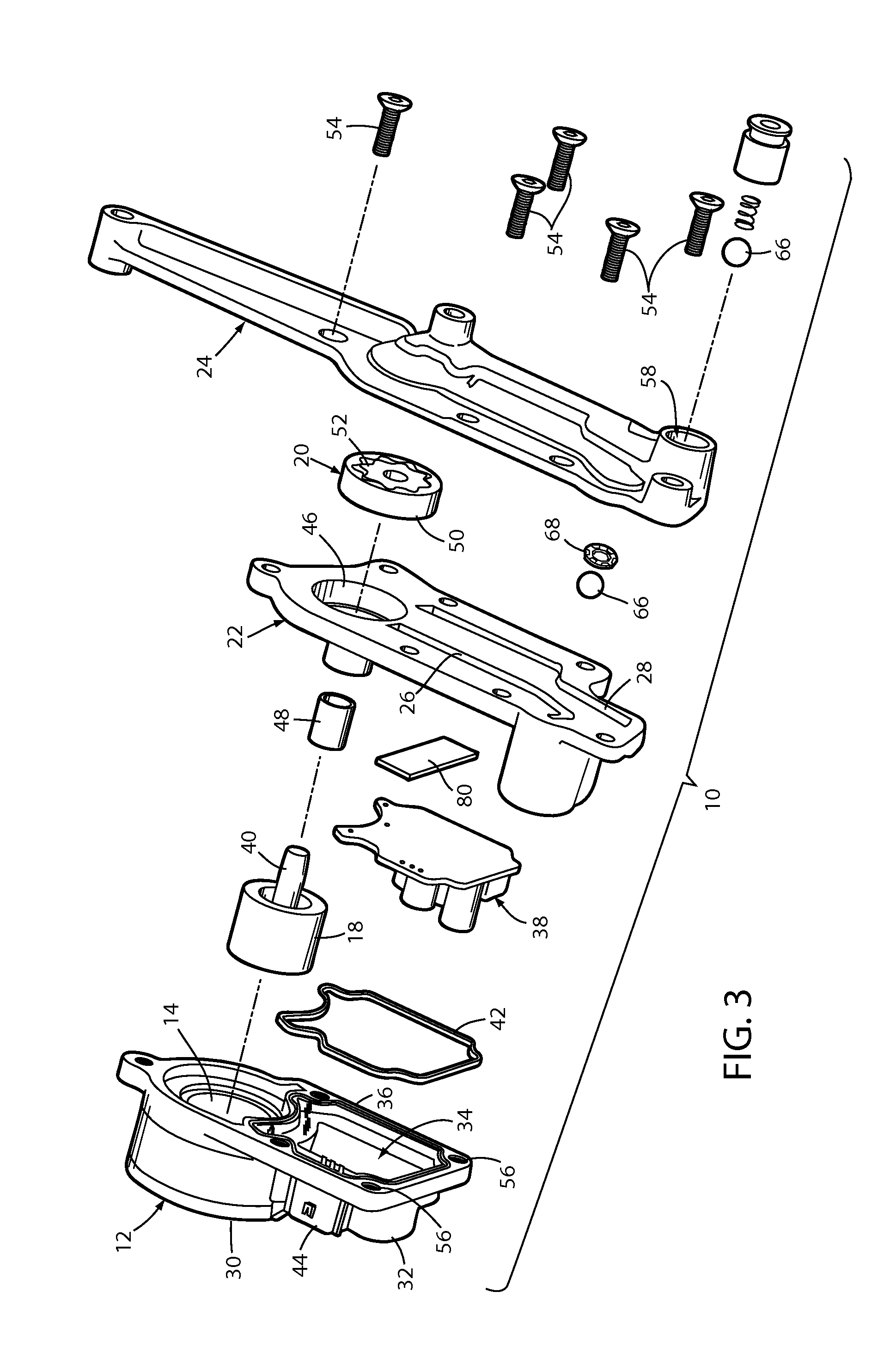
[0035]For purposes of description herein, the terms “upper,”“lower,”“right,”“left,”“rear,”“front,”“vertical,”“horizontal,” and derivatives thereof shall relate to the pump assembly embodiment as oriented in FIG. 1. However, it is to be understood that the pump assembly may assume various alternative orientations, except where expressly specified to the contrary. It is also to be understood that the specific devices and processes illustrated in the attached drawings, and described in the following specification are simply exemplary embodiments of the inventive concepts. Hence, specific dimensions and other physical characteristics relating to the embodiments disclosed herein are not to be considered as limiting, unless expressly state otherwise.

[0036]Referring to embodiments illustrated in FIGS. 1-16, reference numeral 10 is used to generally designate a pump assembly that is configured for transferring automatic transmission fluid (ATF) to associated engine components. The pump asse...


PUM

PropertyMeasurementUnit
temperatureaaaaaaaaaa
magnetic fluxaaaaaaaaaa

Abstract

A pump assembly includes an electric motor and different selectable pump covers, and is suitable for mounting within a transmission fluid reservoir for transferring automatic transmission fluid. The pump assembly includes a stator housing having a cylindrical cavity for receiving ATF contained in the transmission fluid reservoir. A rotor is rotatably coupled within the cylindrical cavity and has a plurality of magnets arranged about a rotational axis thereof. A flux collector is coupled with the stator housing adjacent to the cylindrical cavity for transferring magnetic flux from one of the plurality of magnets from a first portion to a second portion thereof. A hall sensor is disposed proximate the second portion for sensing magnetic flux in the flux collector, such that the magnetic flux is used to determine a rotated position of the rotor.

Description

[0001]This application claims benefit under 35 USC section 119(e) to U.S. Provisional Application No. 61 / 987,279, filed on May 1, 2014, entitled “SUBMERSIBLE TRANSMISSION FLUID PUMP ASSEMBLY,” the disclosure of which is hereby incorporated herein by reference in its entirety.FIELD OF THE INVENTION[0002]The present invention generally relates to pump assemblies that may be submersed in fluid, and more particularly relates to a transmission fluid pump assembly that may be packaged in several different transmission variants, such as transmissions for different vehicles and engine configurations.BACKGROUND[0003]Many factors drive vehicle design, including increasing gas mileage standards and a desire to maintain or increase performance capability. As engine space for vehicles becomes more constricted, many changes are presented to improve engine performance while adhering to the space constraints in vehicles. More specifically, each vehicle model tends to have individually unique constr...

Claims


Application Information

Patent Timeline
Patent Type & Authority Applications(United States)
IPC IPC(8): F04D13/08F04D3/00
CPCF04D13/08Y10T29/49247F04D3/00F04C2/102F04C15/008F04C2240/40F04C2240/81H02K29/08H02K5/04H02K2213/09H02K2213/12H02K11/215H02K11/33F04C13/008F04C2/14
Inventor ROSINSKI, RYAN DAVID
Owner GHSP
Why Eureka
Try Eureka