
Locking catch and latch for quick connect hydraulic coupler

a hydraulic coupler and latch technology, applied in the direction of hose connection, sleeve/socket joint, pipe-joint, etc., can solve the problems of difficult coupling task, difficult pulling the sleeve against the spring, and difficulty in connecting the lines

Inactive Publication Date: 2015-11-05
MULLIN KEVIN
View PDF5 Cites 2 Cited by
  • Summary
  • Abstract
  • Description
  • Claims
  • Application Information

AI Technical Summary

Benefits of technology

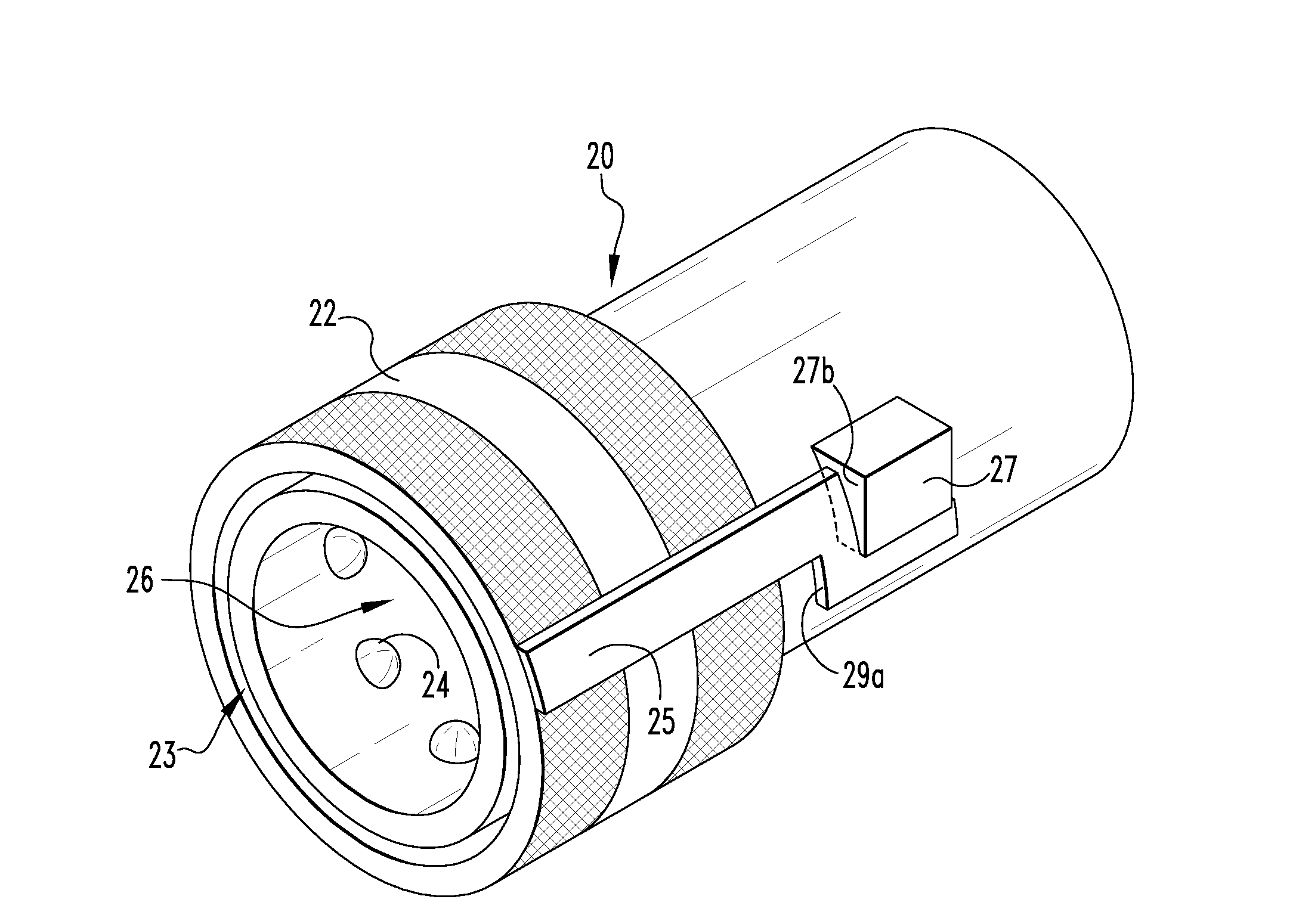
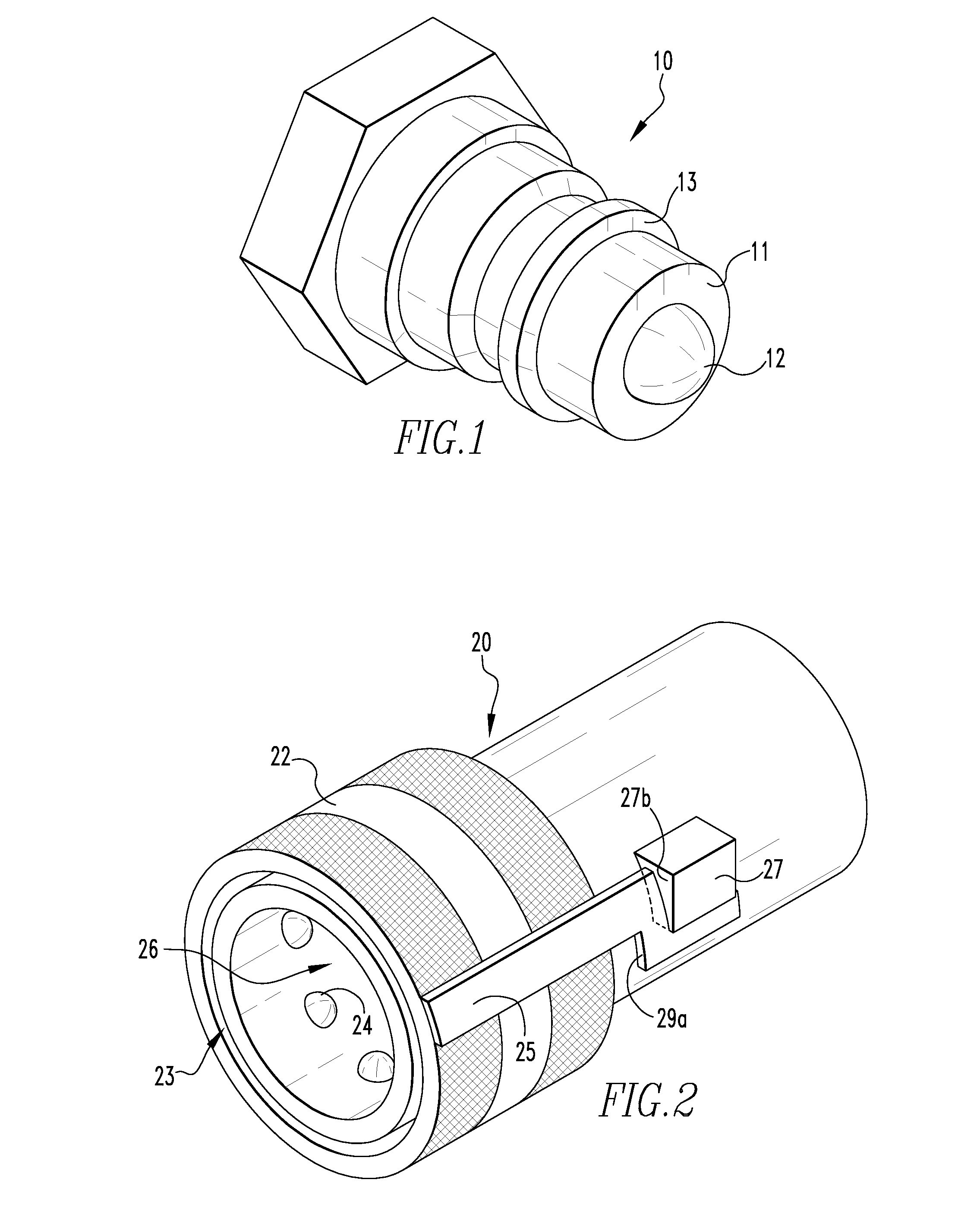
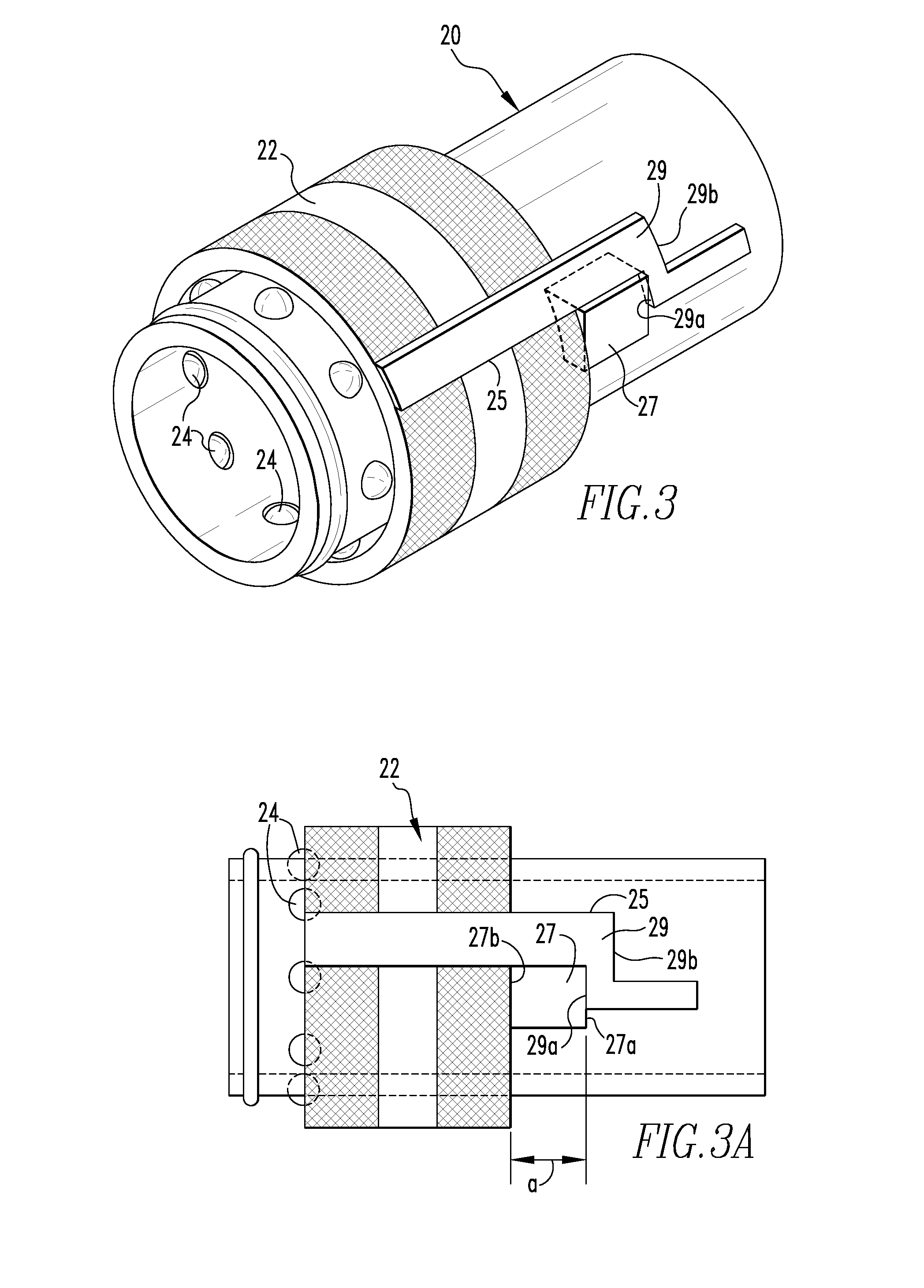
The present invention is a quick connect hydraulic / air coupler with a double locking mechanism. This mechanism consists of a latch and catch integrated into the female coupler and the male fitting, or a separate catch attached to the female coupling member. The double locking means is positioned on the sleeve and coupling member so that the catch can fully insert to the slot and engage the offset of the slot as the sleeve is rotated and moved to its fully retracted position. The sleeve can be then optionally rotated so that the catch engages a rest located in the side of the sleeve facing the female coupling member and on either side of the slot opening. This prevents the sleeve from axially moving away from engaged couplings, and thereby, preventing a disconnection of the two members. The invention simplifies the process of joining the couplers, reduces the risk of accidental disconnects, and makes it easier to clean and maintain the female coupler.

Problems solved by technology

There are, however, a number of problems associated with their use.
For example, there are many times that there is pressure in the lines from the hydraulic fluid which causes difficulty in connecting the lines.
Also, the design of the female coupler makes the coupling task very difficult, especially in cold or wet weather.
Thus, pulling the sleeve against the springs is very difficult.
Making this task more difficult is that one needs one hand to pull the sleeve in the opposite direction from the mating coupler.
Because of the location of the hydraulic lines, it is often times very difficult for the operator to hold the coupling flange backwards while attempting to align the male fitting into the coupler.
Additionally, the grip on the fitting is difficult if the fitting is wet or oily and / or if there is residual pressure in the line.
Another flaw with the female coupler is that it is difficult to clean.
Over time debris invades the inside of the female coupler.
Rust, dirt, fluid and other substances tend to get under the sleeve and around the ball bearings.
Thus, cleaning the female coupler is more difficult than it should be.
Even a person with great hand strength eventually loses grip and tires quickly.
However, while pressure from the fluid or air is cycling through, or has been cycling through and the machines turned off, it takes very little for the lines to accidentally disconnect.
However, even with this, it can be an unnecessary hassle and, at times, can be dangerous to the equipment and the operator.

Method used


Image

  • Locking catch and latch for quick connect hydraulic coupler
  • Locking catch and latch for quick connect hydraulic coupler
  • Locking catch and latch for quick connect hydraulic coupler

Examples


Embodiment Construction

[0006]The present invention overcomes the problems described above by using a novel double locking means mounted to the movable sleeve on the female coupler. On the nonmoveable portion of the coupler is a catch mounted at the terminus of female sleeve's movement from the receiving end coupler. In a preferred embodiment of the invention, the double locking means comprises a latch configured as a slot and offset that is integrally formed into the female's movable sleeve, together with a catch that is attached to the female coupling member. The double locking means is positioned on the sleeve and female coupling member so that the catch can fully insert to the slot and engage the offset of the slot as the sleeve is rotated and moved to its fully retracted position. When the male fitting is engagedly positioned into the female, the sleeve is rotated to disengage the catch from the offset and out of the slot to permit the sleeve to fully encompass the mating portion of the male fitting. ...


PUM


Abstract

A double locking mechanism for male and female fluid coupling members that can lock the moveable sleeve on the female member in the open position to facilitate coupling with the male member, or in the closed position to prevent male member from disconnecting from female member. A catch is integrated with the nonmoveable portion of the female coupler and a latch such as a slot and offset is integrally formed in the female member's movable sleeve. Alternatively, the latch can attached or be integrally with, and extend from, the movable sleeve in the direction of the female coupler. The movable sleeve is retracted and rotated such that the latch engages the catch to lock the sleeve in an open position. When the male member is fully engaged with the female member, the movable sleeve is rotated so that the latch engages the catch to lock the sleeve in a closed position.

Description

CROSS-REFERENCE TO RELATED APPLICATIONS[0001]This application is a Continuation-in-Part Application that claims the benefit of U.S. application Ser. No. 14 / 181,764, filed Feb. 17, 2014, which, in turn, claims the benefit of U.S. Provisional Application Ser. No. 61 / 789,033, titled LOCKING CATCH AND LATCH FOR QUICK CONNECT HYDRAULIC COUPLER, filed Mar. 15, 2013, which is incorporated by reference herein.BACKGROUND OF THE INVENTION[0002]The present invention relates to quick connect hydraulic couplers. These hydraulic couplers are used in many industries for connecting hydraulic fluid lines. Many are used in the transportation industry to connect trailers to their tractors or hydraulic equipment in the field. The quick connect hydraulic coupler products currently available are very useful in joining hydraulic lines together. There are, however, a number of problems associated with their use. For example, there are many times that there is pressure in the lines from the hydraulic fluid ...

Claims


Application Information

Patent Timeline
IPC IPC(8): F16L21/08
CPCF16L21/08F16L37/23F16L35/00F16L37/138
Inventor MULLIN, KEVIN
Owner MULLIN KEVIN
Learn More