Propellant flow actuated piezoelectric igniter for combustion engines

a piezoelectric igniter and propellant flow technology, which is applied in the direction of generator/motor, lighting and heating apparatus, transportation and packaging, etc., can solve the problem that none of these prior inventions have been practically successful in solving this problem, and achieve a strong and reliable spark response, and a better method of igniting the rocket propulsion system

Inactive Publication Date: 2015-11-05
INNOVATIVE ENG SOLUTIONS
View PDF0 Cites 0 Cited by
  • Summary
  • Abstract
  • Description
  • Claims
  • Application Information

AI Technical Summary

Benefits of technology

The invention is about a device that can produce a strong and reliable spark to ignite a rocket engine or gas turbine engine. The goal is to improve the process of igniting rocket engines.

Problems solved by technology

Prior piezoelectric ignition systems have been patented but in prior patented devices it is not clear that as a practical matter sufficient force will be generated by any of the described methods, or that the impulse applied to the crystal will be of sufficient magnitude or be applied at a rapid enough rate to produce a strong spark.
However, each one of these references suffers from one or more of the above disadvantages related to insufficiency of spark strength:
In an attempt to produce a satisfactory spark strength, some prior patents have attempted to solve this problem by describing possible methods of spreading the gas pressure over a larger area, and attempting to increase the force applied to the piezoelectric crystal proposing to use impingement of the gas force directly onto the piezoelectric crystal, or through an attached intermediary connecting element, but to date none of these prior inventions have been practically successful in solving this problem.

Method used


Image

  • Propellant flow actuated piezoelectric igniter for combustion engines
  • Propellant flow actuated piezoelectric igniter for combustion engines
  • Propellant flow actuated piezoelectric igniter for combustion engines

Examples


Embodiment Construction

[0024]Detailed descriptions of the preferred embodiment are provided herein. It is to be understood, however, that the present invention may be embodied in various forms. Therefore, specific details disclosed herein are not to be interpreted as limiting, but rather as a basis for the claims and as a representative basis for teaching one skilled in the art to employ the present invention in virtually any appropriately detailed system, structure or manner.

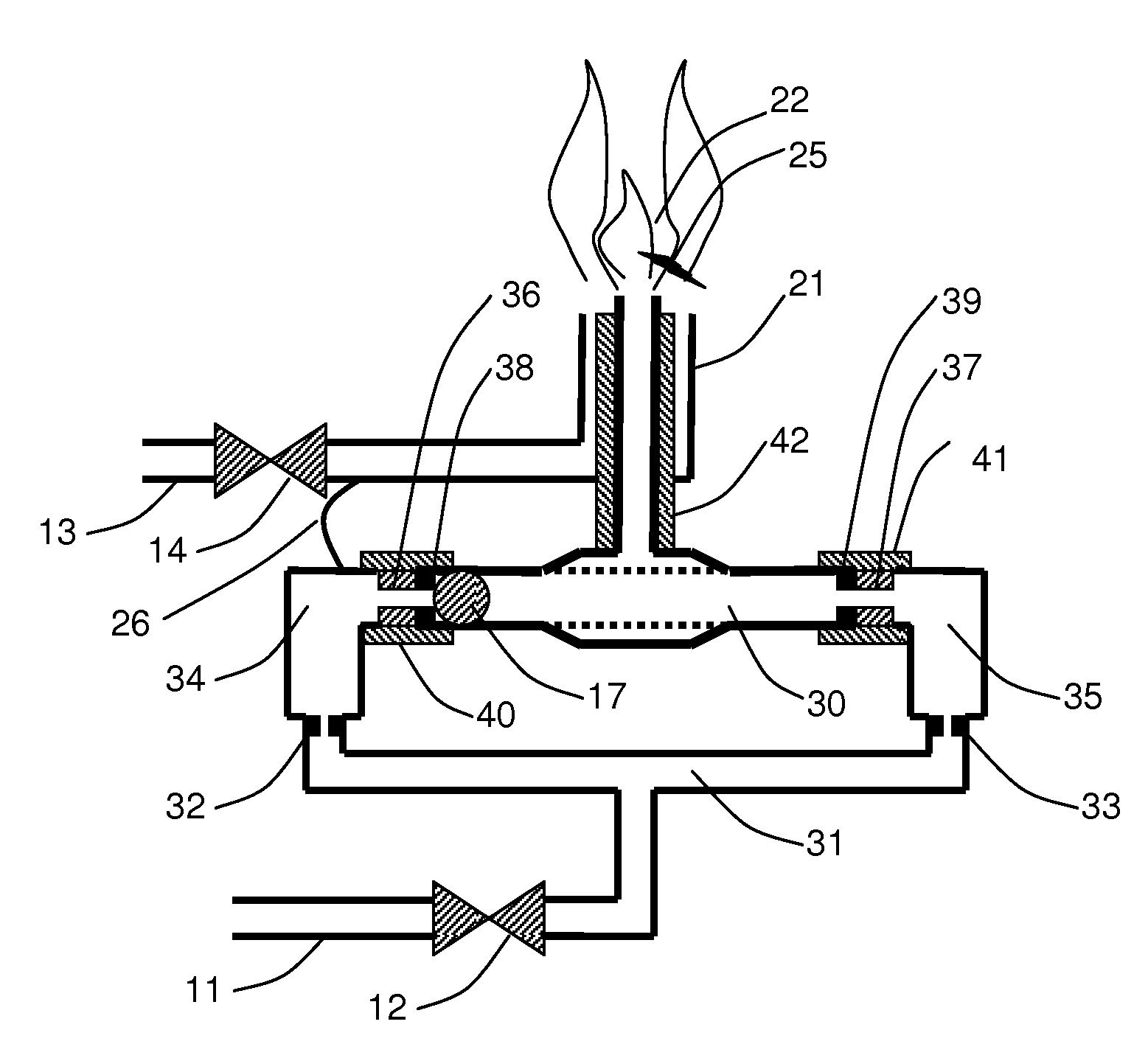
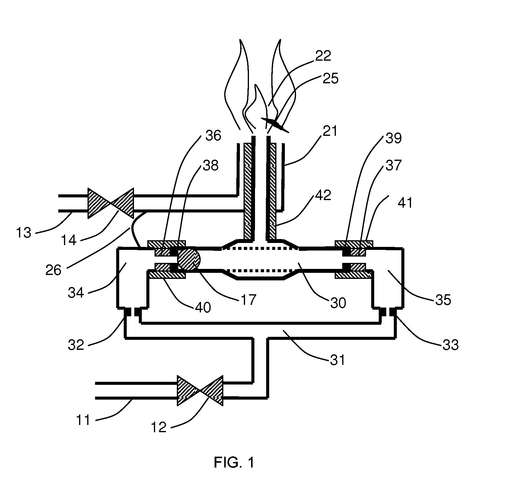
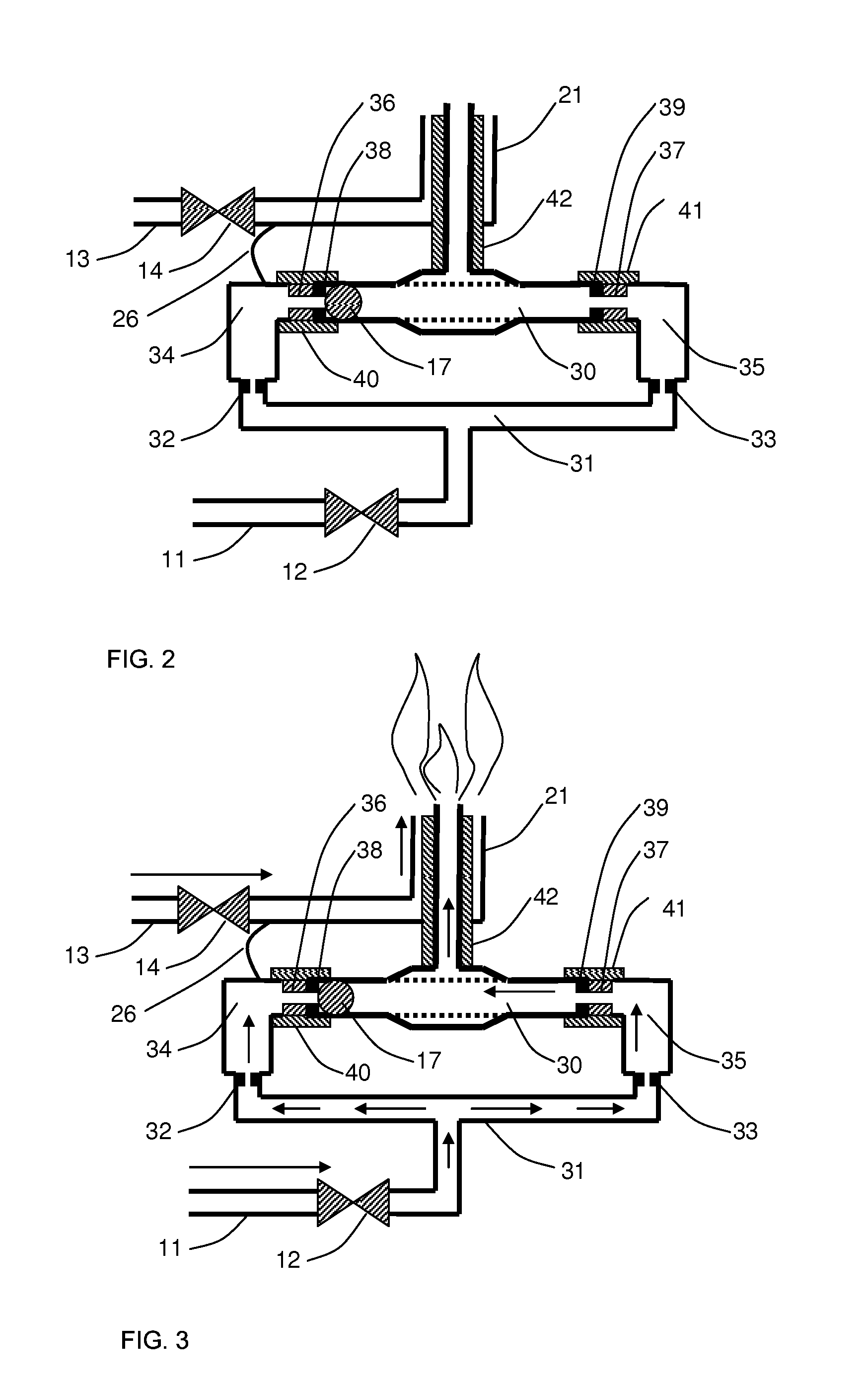
[0025]FIG. 1 shows an embodiment capable of driving a hammer ball in an oscillating manner, wherein each magnet is in contact with a piezoelectric crystal thereby functioning as an anvil (anvil magnet), thereby producing a repetitive series of sparks when gas flow is supplied. The hammer ball is driven alternately from one side to the other, impacting anvil magnets at each end, and causing the piezoelectric crystals to create repetitive discharge sparks.

[0026]In this embodiment, there are two piezoelectric crystals (36) and (37), eac...


PUM


Abstract

A propellant flow actuated piezoelectric igniter device using one or more hammer balls retained by one or more magnets, or other retaining method, until sufficient fluid pressure is achieved in one or more charging chambers to release and accelerate the hammer ball, such that it impacts a piezoelectric crystal to produce an ignition spark. Certain preferred embodiments provide a means for repetitively capturing and releasing the hammer ball after it impacts one or more piezoelectric crystals, thereby oscillating and producing multiple, repetitive ignition sparks. Furthermore, an embodiment is presented for which oscillation of the hammer ball and repetitive impact to the piezoelectric crystal is maintained without the need for a magnet or other retaining mechanism to achieve this oscillating impact process.

Description

CROSS REFERENCE TO RELATED APPLICATIONS[0001]This is a division of application Set. Nr. 12 / 906,360 Filed 18 Oct. 2010.STATEMENT REGARDING FEDERALLY SPONSORED RESEARCH OR DEVELOPMENT[0002]A portion of the research related to an embodiment of the present invention was partially funded by a Federally funded government contract under NASA Small Business Research and Development (SBIR) Phase I contract number NNX10CD19P, issued to Innovative Engineering Solutions on 29 Jan. 2010 and completed on 29 Jul. 2010.DESCRIPTION OF ATTACHED APPENDIX[0003]Not ApplicableBACKGROUND OF THE INVENTION[0004]Because of the severe stress put on the ignition of rocket engines in rocket powered systems, gas turbine engines, and other similar combustion devices, and the catastrophic result of a failure to timely and reliably ignite them, there has always been a need for a reliable engine igniter which would be able to be accurately timed to ignite when desired.[0005]Piezoelectric crystals have been used com...

Claims


Application Information

Patent Timeline
Patent Type & Authority Applications(United States)
IPC IPC(8): F23Q3/00F02P3/12
CPCF02P3/12F23Q3/002Y10T292/0809Y10T137/7905Y10T292/11Y10T292/14H02N2/183H02N2/185
Inventor WOLLEN, MARK A.
Owner INNOVATIVE ENG SOLUTIONS
Why Eureka
Try Eureka