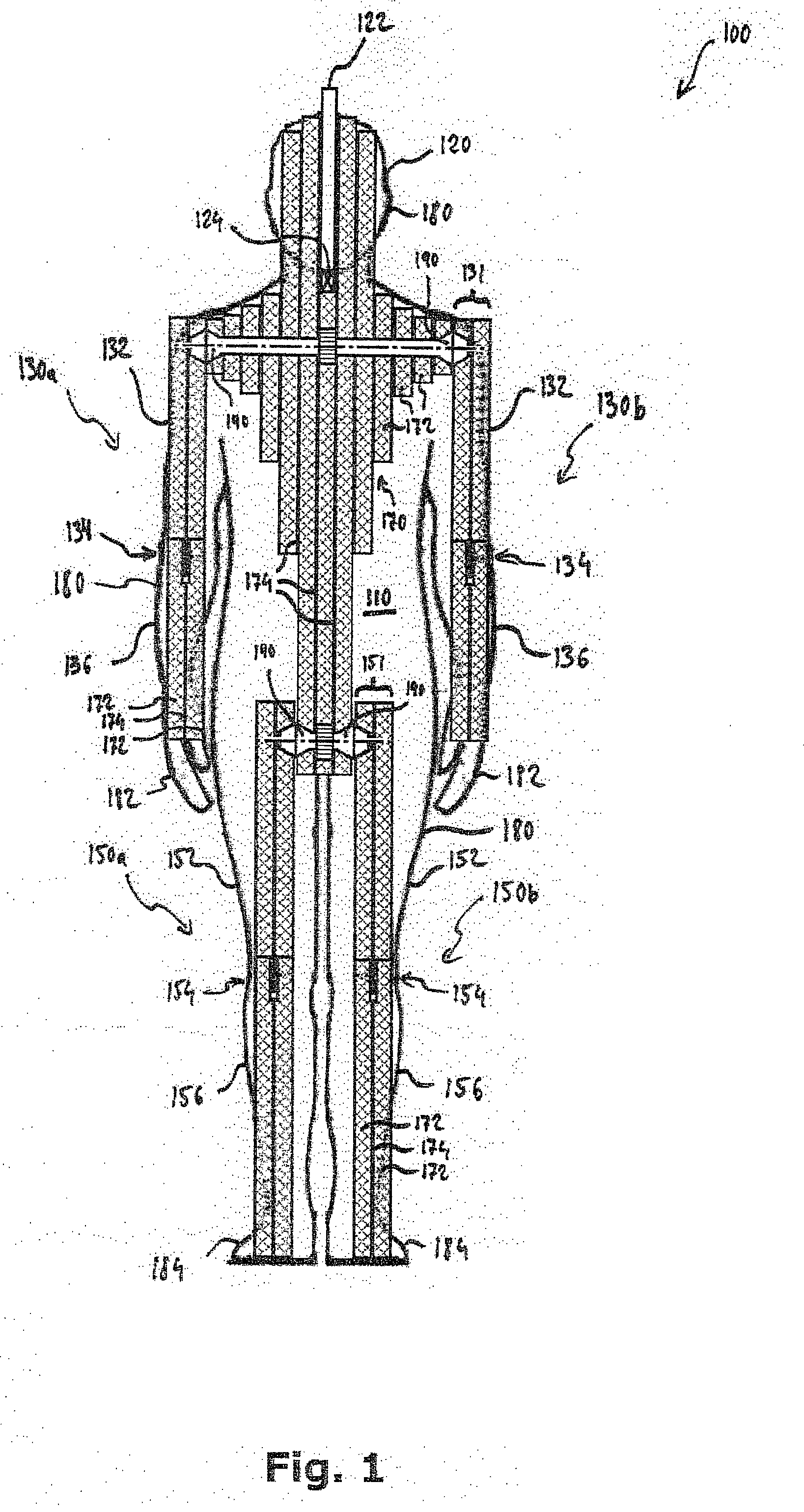
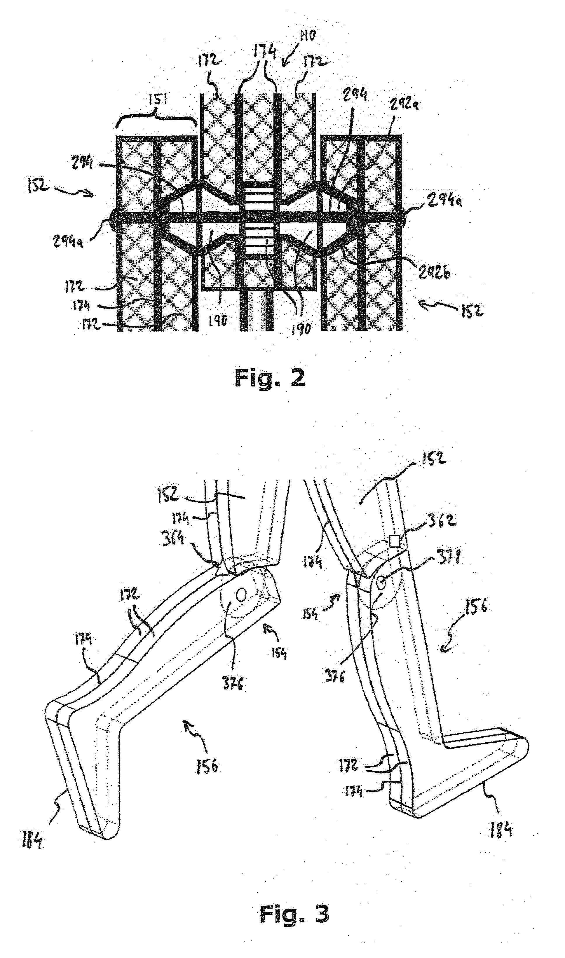
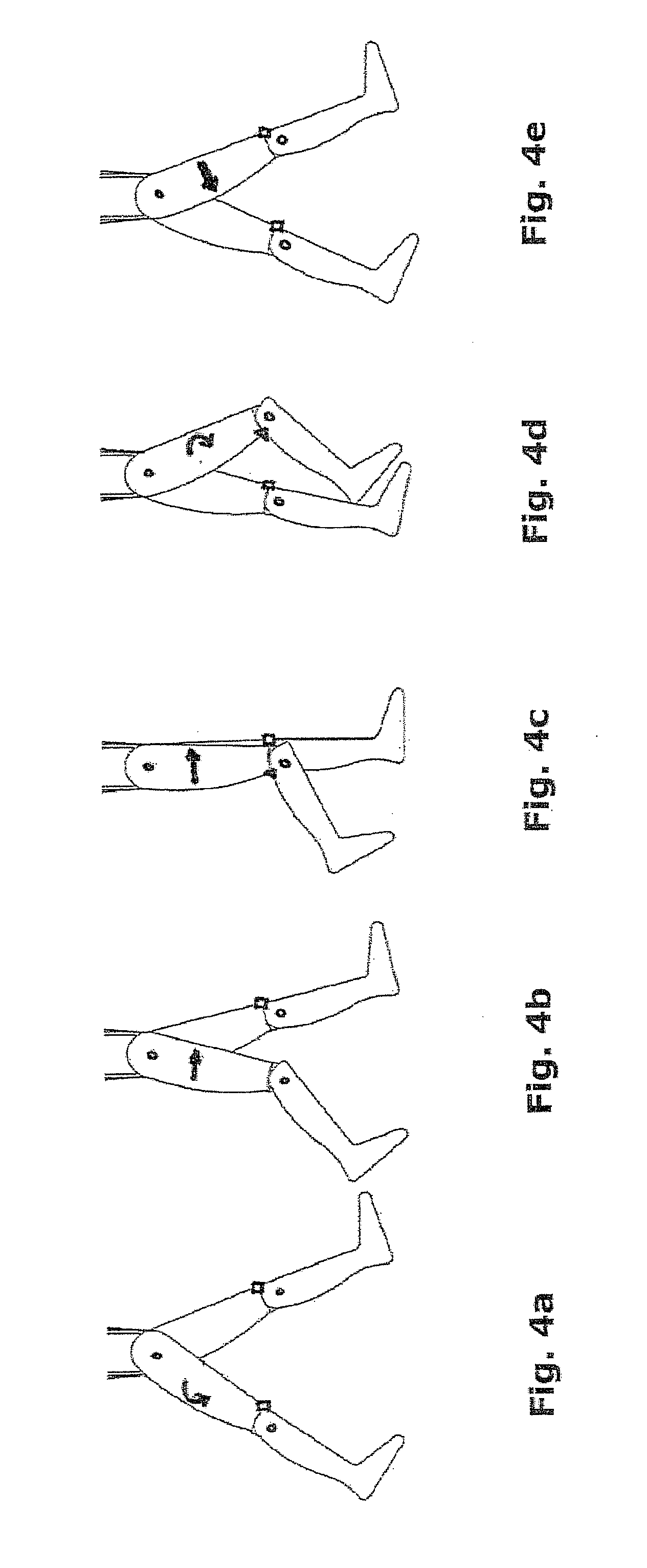
Dummy object with extremeties which utilise the mass inertia thereof to replicate a natural movement process
a technology of extremeties and dummy objects, applied in the field of dummy objects, can solve the problems of difficult detection and identification of pedestrians, incorrect data in the development and testing of driver assistance systems, and the movement behavior of pedestrians in road traffic is relatively complex, so as to achieve the effect of improving the robustness of the dummy object, and reducing the risk of injury
- Summary
- Abstract
- Description
- Claims
- Application Information
AI Technical Summary
Benefits of technology
Problems solved by technology
Method used
Image

Examples
Embodiment Construction
[0081]It is pointed out that features or components of different embodiments which are identical or at least functionally identical to the corresponding features or respectively components according to the respective embodiment, are provided with identical reference numbers or are provided with reference numbers which merely differ in the first number from the reference number of the identical or at least functionally identical features or respectively components. To avoid unnecessary repetitions, features or components already explained by means of a previously described embodiment are not explained in further detail at a later point.
[0082]In addition, it is pointed out that the embodiments described below represent merely a limited selection of possible design variants of the invention. In particular, it is possible to combine the features of individual embodiments with one another in a suitable manner, so that with the design variants illustrated explicitly here, a plurality of d...
PUM
 Abstract
Description
Claims
Application Information