
Method and Tuning Device for Tuning a Tunable Optical Transmitter to a Predetermined Target Wavelength

a technology of optical transmitter and target wavelength, which is applied in the direction of electrical apparatus, transmission, electromagnetic transmission, etc., can solve the problems of low-cost optical tunable transmitter, which cannot guarantee the (center) use of such low-cost tunable transmitter, and achieve the effect of low-cost optical wdm system

Active Publication Date: 2015-11-05
ADVA OPTICAL NETWORKING SE
View PDF6 Cites 9 Cited by
  • Summary
  • Abstract
  • Description
  • Claims
  • Application Information

AI Technical Summary

Benefits of technology

This patent describes methods and devices for tuning optical transmitters in a way that ensures they are working properly without affecting other optical channels in the system. This is important during the power-on procedure of the transmitter and helps to minimize disruption to the overall cost of the system. The goal is to make optical WDM systems more reliable and efficient.

Problems solved by technology

Thus, a low-cost optical tunable transmitter may be used which cannot guarantee that the (center) wavelength of the optical signal created in the switch-on-state lies within the wavelength range of the respective dedicated optical channel of the WDM system with sufficient accuracy.
Using such low-cost tunable transmitters was impossible when realizing a PtP WDM system as, during the switch-on-state, it would have been highly probable that the respective optical signal has a (center) wavelength such that the respective (narrow-band) optical spectrum of the optical signal interferes with the spectrum of another optical channel signal created by another optical transmitter.

Method used


Image

  • Method and Tuning Device for Tuning a Tunable Optical Transmitter to a Predetermined Target Wavelength
  • Method and Tuning Device for Tuning a Tunable Optical Transmitter to a Predetermined Target Wavelength
  • Method and Tuning Device for Tuning a Tunable Optical Transmitter to a Predetermined Target Wavelength

Examples


Embodiment Construction

[0044]In the following, embodiments of the invention will be described with reference to an NG-PON2 WDM-PON as defined in the ITU Recommendation ITU-T G.989.1. However, as apparent to one familiar with the field of designing WDM transmission systems or networks, embodiments of the invention may be applied to any other type of a PON in which the above-identified problem in connection with the use of relatively low-cost and only coarsely calibrated optical transmitters arises.

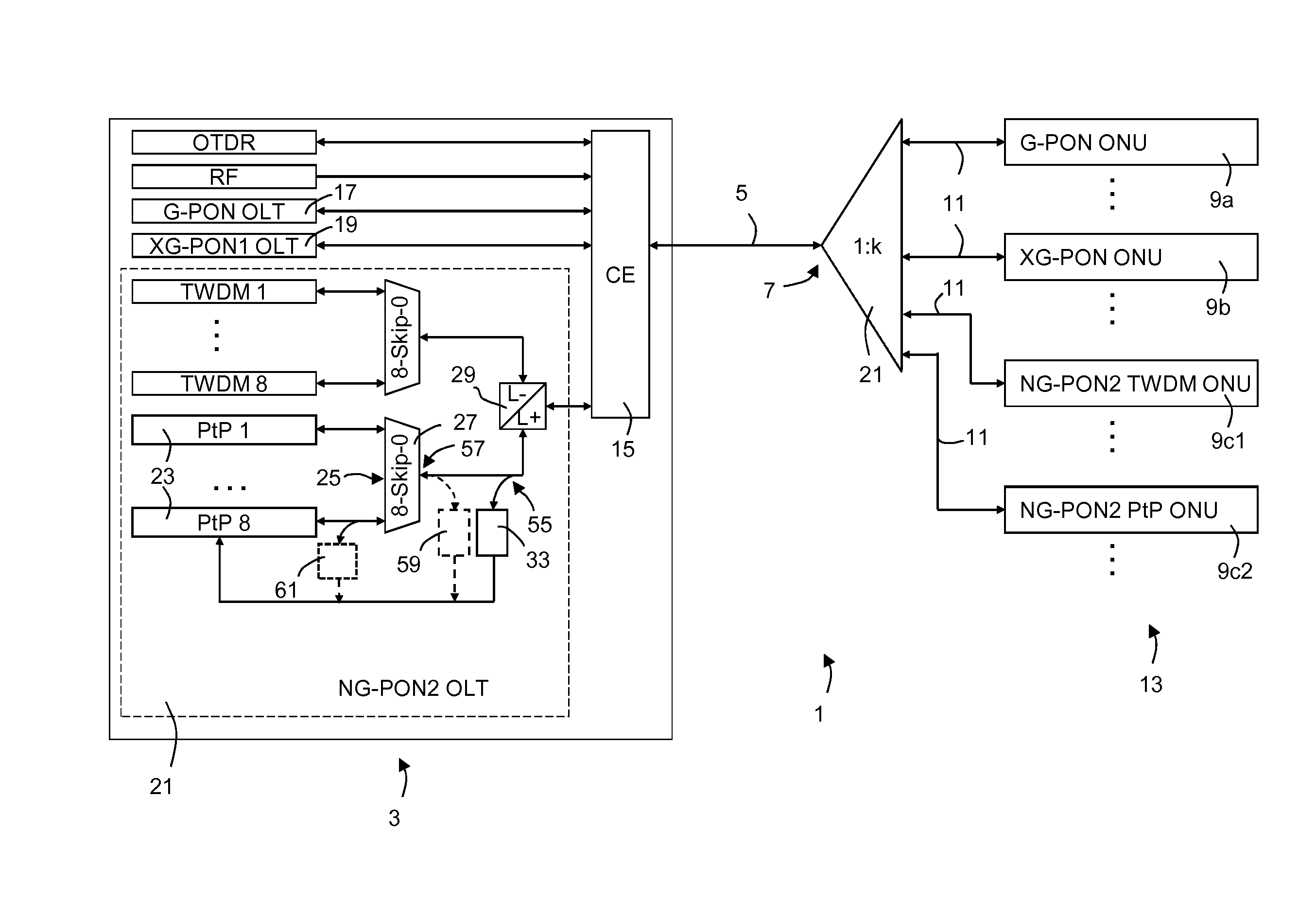
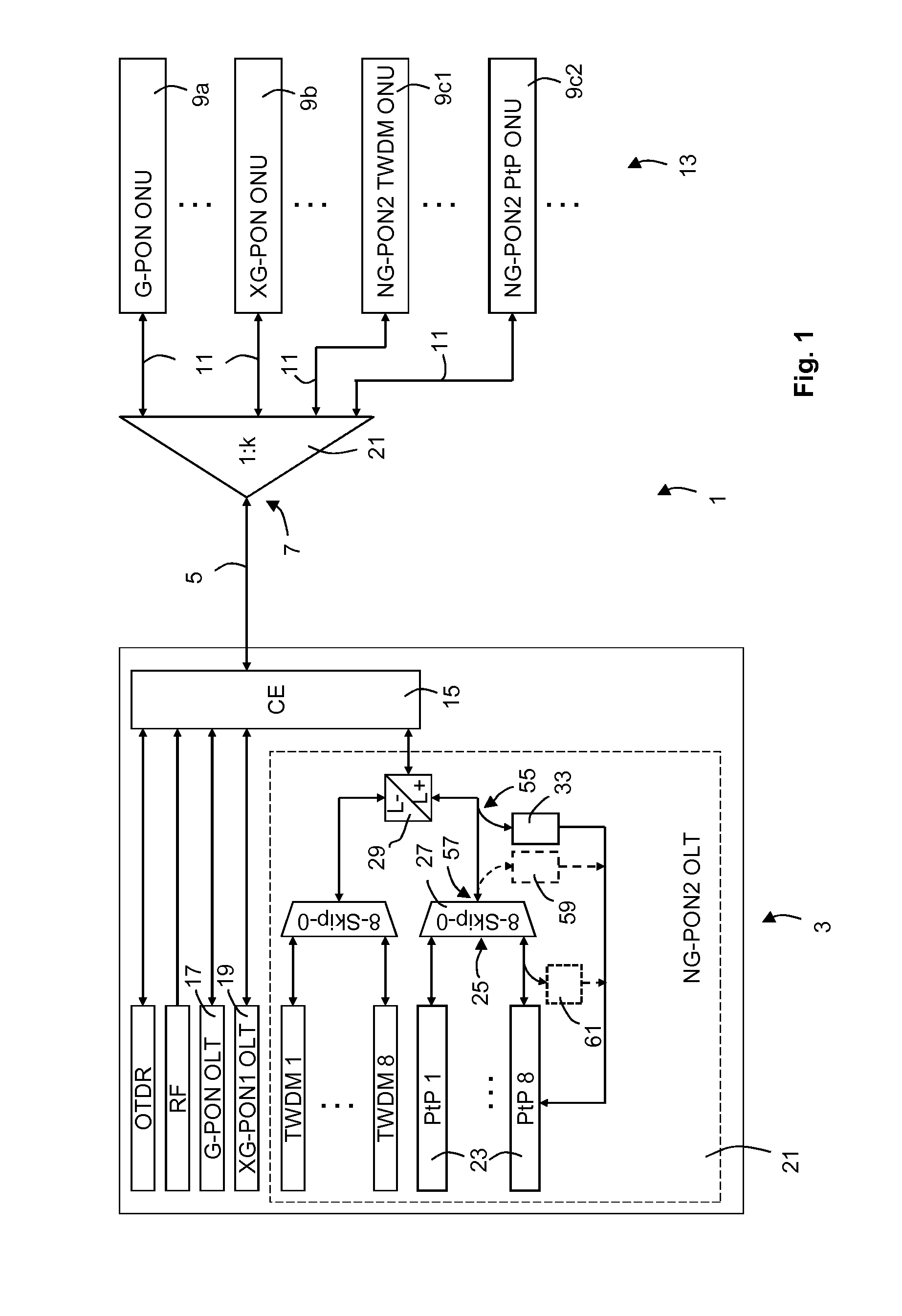
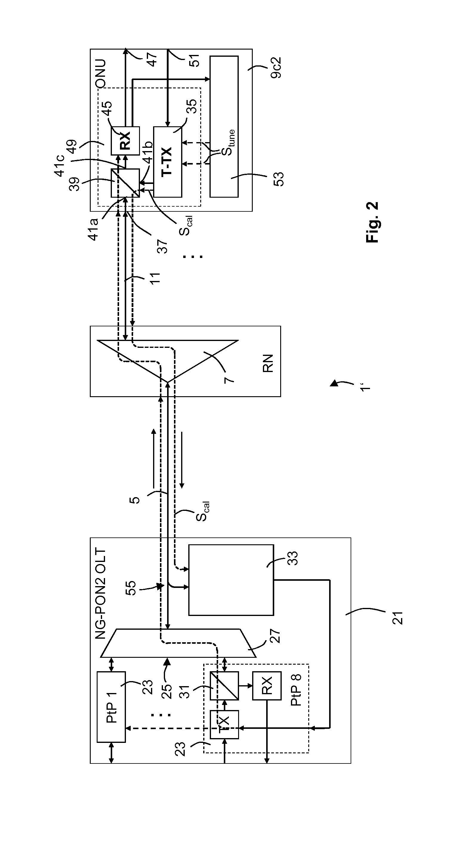
[0045]FIG. 1 shows an optical WDM system in the form of a WDM-PON 1 according to a first embodiment of the invention. In general, a PON comprises at least one OLT at the central node side 3, which is connected via a WDM transmission link 5, e.g. an optical fiber, to a remote node (RN) 7, which is configured to connect a plurality of ONUs 9a, 9b, 9c1, and 9c2 to the RN 7 by a respective distribution link 11, e.g. an optical distribution fiber. The ONUs represent the customer side 13 of the PON 1. Of course, as sho...


PUM


Abstract

A method for tuning a tunable optical transmitter to a target wavelength includes applying at least one tuning signal to the tunable optical transmitter to control the tunable optical transmitter to create an optical calibration signal according to nominal tuning information for the tunable optical transmitter. The optical calibration signal has a wavelength lying within a secure wavelength range, and the nominal tuning information is based on a nominal wavelength dependency for the tunable optical transmitter. The method also includes measuring a deviation between an actual wavelength dependency of the tunable optical transmitter and the nominal wavelength dependency, and determining calibration information based on that deviation. The calibration information is applied to determine a corrected nominal wavelength dependency from which target tuning information is determined. The tunable optical transmitter is controlled to create an optical channel signal according to the target tuning information.

Description

TECHNICAL FIELD OF THE INVENTION[0001]The invention relates to methods for tuning a tunable optical transmitter of a given type out of a plurality of optical transmitters that are connected to a first end of an optical wavelength division multiplex (WDM) transmission link to a predetermined target wavelength, especially during a power-on procedure of the tunable optical transmitter. Further, the invention relates to tuning control devices for at least one tunable optical transmitter adapted to be used in an optical WDM system, the tuning control devices realizing the respective method, and to optical WDM systems including such a tuning control device.BACKGROUND OF THE INVENTION[0002]In optical wavelength division multiplex (WDM) passive optical networks (PONs) a plurality of optical network units (ONUs) are connected to a central node, also referred to as optical line terminal (OLT). PONs enable a bi-directional point-to-point (PtP) connection between each ONU and the OLT using dedi...

Claims


Application Information

Patent Timeline
Patent Type & Authority Applications(United States)
IPC IPC(8): H04B10/572H04J14/02H04B17/11
CPCH04B10/572H04J14/02H04B17/11H04B10/506H04J14/0307
Inventor GROBE, KLAUSEISELT, MICHAEL
Owner ADVA OPTICAL NETWORKING SE
Learn More